


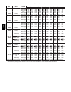
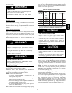
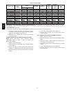

22
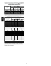
Table 7—Electrical Data
FURNACE SIZE
VO LT S ---
H ER TZ ---
PHASE
OPERATING VOLTAGE
RANGE
MAXIMUM
UNIT AMPS
UNIT
AMPACITY#
MAXIMUM
WIRE
LENGTH FT.
(M)‡
MAXIMUM
FUSE OR
CKT BKR
AMPS†
MINIMUM
WIRE
GAUGE
Maximum*
Minimum*
045---08/024045 115 --- 6 0 --- 1 127 104 5.2 7.26 49 (14.9) 15 14
045---12/036045 115 --- 6 0 --- 1 127 104 7.2 9.79 37 (11.2) 15 14
070---08/024070 115 --- 6 0 --- 1 127 104 5.1 7.14 51 (15.5) 15 14
070---12/036070 115 --- 6 0 --- 1 127 104 7.2 9.72 38 (11.5) 15 14
070---16/048070 115 --- 6 0 --- 1 127 104 9.5 12.60 29 (8.8) 15 14
090---14/042090 115 --- 6 0 --- 1 127 104 8.6 11.39 32 (9.7) 15 14
090---16/048090 115 --- 6 0 --- 1 127 104 10.0 13.09 28 (8.5) 15 14
090---20/060090 115 --- 6 0 --- 1 127 104 14.1 18.2 31 (9.4) 20 12
110---12/036110 115 --- 6 0 --- 1 127 104 8.6 11.27 32 (9.7) 15 14
110---16/048110 115 --- 6 0 --- 1 127 104 10.2 13.34 27 (8.2) 15 14
110---22/066110 115 --- 6 0 --- 1 127 104 15.1 19.42 29 (8.8) 20 12
135---16/048135 115 --- 6 0 --- 1 127 104 10.5 13.63 27 (8.2) 15 14
135---22/066135 115 --- 6 0 --- 1 127 104 14.5 18.72 30 (9.1) 20 12
155---20/060155 115 --- 6 0 --- 1 127 104 15.4 19.83 29 (8.8) 20 12
* Permissible limits of the v oltage range at which the unit o perates satisfactorily.
# Unit ampacity = 125 percent of largest operating component’s full load amps plus 100 percent of all other potential operating components’ (EAC, humidifier,
etc.) full load amps.
{ Time---delay type is recommended.
} Length shown is as measured 1 way along wire path between unit and service panel for maximum 2 percent voltage drop.
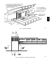
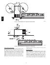
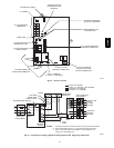
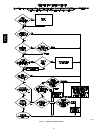
12. Complete electrical box wiring and installation. Connect
line voltage leads as shown in Fig. 26. Use best practices
(NEC) for wire bushings, strain relief, etc.
13. Reinstall cover to J--Box. Do not pinch wires between
cover and bracket.
POWER CORD INSTALLATION IN FURNACE J--BOX
NOTE: Power cords must be able to handle the electrical
requirements listed in Table 7. Refer to power cord
manufacturer’s listings.
1. Remove cover from J--Box.
2. Route listed power cord through 7/8--in. (22 mm) diameter
hole in J--Box.
3. Secure power cord to J--Box bracket with a strain relief
bushing or a connector approved for the type of cord used.
4. Secure field ground wire to green ground screw on J--Box
bracket.
5. Connect line voltage leads as shown in Fig. 26.
6. Reinstall cover to J--Box. Do not pinch wires between
cover and bracket.
BX CABLE INSTALLATION IN FURNACE J--BOX
1. Remove cover from J--Box.
2. Route BX cable into 7/8--inch (22 mm) diameter hole in
J--Box.
3. Secure BX cable to J--Box bracket with connectors ap-
proved for the type of cable used.
4. Secure field ground wire to green ground screw on J--Box
bracket.
5. Connect line voltage leads as shown in Fig. 26.
6. Reinstall cover to J--Box. Do not pinch wires between
cover and bracket.
310AAV