


34
ELECTRICAL SHOCK HAZARD
Failure to follow this warning could result in personal
injury or death.
Disconnect 115--v electrical power and install lockout tag
before changing speed tap.
!
WARNING
c. Adjust air temperature rise by adjusting blower speed.
Increase blower speed to reduce temperature rise.
Decrease blower speed to increase temperature rise.
d. Turn thermostat down below room temperature and
remove blower access door.
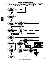
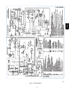
e. To change motor speed selection for heating, remove
blower motor lead from control HEAT terminal (See
Fig. 25.) Select desired blower motor speed lead from
one of the other terminals and relocate it to the HEAT
terminal (See Table 12 for lead color identification).
Reconnect original lead to SPARE terminal.
Table 12—Speed Selection
COLOR SPEED AS SHIPPED
White Common BLW
Black High COOL
Yellow{ Me d --- Hig h SPARE
Blue* Med --- L ow SPARE
Red* Low HEAT
* 1/5 H P motor models: BLUE to HEAT, RED to SPARE
{ Nota vailable on 1/5 HP motors.
NOTE: Continuous blower is the HEAT speed.
f. Repeat steps a through e.
g. When correct input rate and temperature rise is
achieved, turn gas valve ON/OFF switch to OFF.
h. Remove manometer or similar device from gas valve.
i. Reinstall manifold pressure tap plug in gas valve.
FIRE HAZARD
Failure to follow this warning could result in personal
injury, death and/or property damage.
Reinstall manifold pressure tap plug in gas valve to
prevent gas leak.
!
WARNING
j. Reinstall blower access door if removed.
k. Turn gas valve ON/OFF switch to ON.
FURNACE OVERHEATING HAZARD
Failure to follow this caution may result in reduced furnace
life.
Recheck temperature rise. It must be within limits specified
on the rating plate. Recommended operation is at the
midpoint of rise range or slightly above.
CAUTION
!
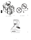
6. Set thermostat heat anticipator.
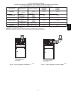
a. Mechanical thermostat -- Set thermostat heat anticipat-
or to match the amp. draw of the electrical components
in the R--W circuit. Accurate amp. draw readings can
be obtained at the wires normally connected to ther-
mostat subbase terminals, R and W. The thermostat
anticipator should NOT be in the circuit while measur-
ing current. (1.) Remove thermostat from subbase or
from wall. (2.) Connect an amp. meter as shown in
Fig. 44 across the R and W subbase terminals or R and
W wires at wall.
(3.) Record amp. draw across terminals when furnace
is in heating and after blower starts.
(4.) Set heat anticipator on thermostat per thermostat
instructions and install on subbase or wall.
b. Electronic thermostat: Set cycle rate for 4 cycles per
hr.
7. Adjust blower off delay The blower off delay has 4 ad-
justable settings from 90 sec to 180 sec. The blower off
delay jumpers are located on the furnace control board.
(See Fig. 25.) To change the blower off delay setting,
move the jumper from one set of pins on the control to the
pins used for the selected blower off delay. Factory off
delay setting is 120 sec.
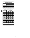
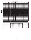
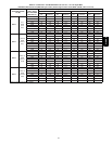
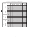
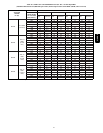
8. Set airflow CFM for cooling Select the desired blower
motor speed lead for cooling airflow. See Table 5--Air De-
livery--CFM (With Filter). See Table 12 for lead color
identification.
310AAV