


29
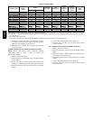
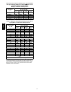
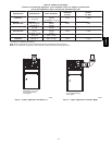
Table 10—Minimum Vent Heights
Caution!! for the following applications, use the minimum vertical vent heights as specified below.
For all other applications, follow exclusively the national fuel gas code.
FURNACE
ORIENTATION
VENT
ORIENTATION
FURNACE
INPUT (BTUH/HR)
MINIMUM VENT
DIAMETER
IN. (mm)*
MINIMUM VERTICAL VENT
HEIGHT
FT. (M)**
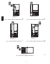
Downflow
Vent elbow l eft, then
up Fig. 32
154,000
132,000
110,000(036/---12 only)
5 ( 127) 12 (3.6)
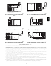
Horizontal Left
Vent elbow right,
then up Fig. 35
154,000
132,000
5 ( 127) 7 ( .65)
Horizontal Left
Vent Elbow up
Fig. 36
154,000
132,000
5 ( 127) 7 ( ,65)
Horizontal Left
Vent elbow right
Fig. 37
154,000 5 (127) 7 (.65)
Downflow
Vent elbow up then
left Fig. 30
110,000
(036/---12 only)
5 ( 127) 10 (3.0)
Downflow
Vent elbow up, then
right Fig. 33
110,000
(036/---12 only)
5 ( 127) 10 (3.0)
* 4 in. ( 102 mm) inside casing o r vent g uard
** Including 4 in. (102 mm) vent section (s)
NOTE: All ven t configurations mu st a lso meet National Fuel Gas Code ( NFGC) venting requirements
NOTE: For all unlisted vent configurations, refer to National Fuel Gas Code (NFGC) venting requirements.
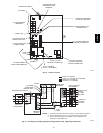
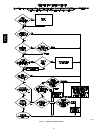
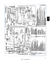
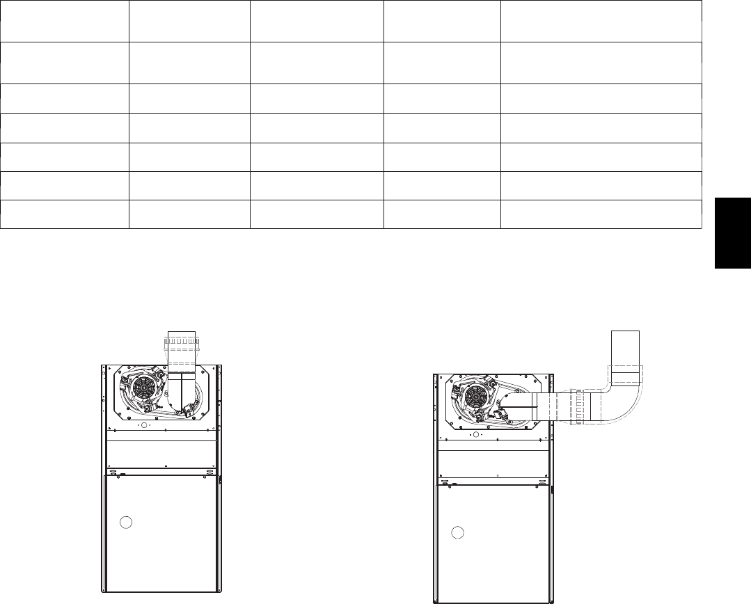
SEE NOTES: 1,2,4,7,8,9
on the page following
these figures
A03208
Fig. 28 --- Upflow Application--Vent Elbow Up
SEE NOTES: 1,2,3,4,7,8,9
on the pages following
these figures
A03209
Fig. 29 --- Upflow Application--Vent Elbow Right
310AAV