


27
APPLIANCE APPLICATION REQUIREMENTS
Appliance operation has a significant impact on the performance
of the venting system. If the appliances are sized, installed,
adjusted, and operated properly, the venting system and/or the
appliances should not suffer from condensation and corrosion.
The venting system and all appliances shall be installed in
accordance with applicable listings, standards, and codes.
The furnace should be sized to provide 100 percent of the design
heating load requirement plus any margin that occurs because of
furnace model size capacity increments. Heating load estimates
can be made using approved methods available from Air
Conditioning Contractors of America (Manual J); American
Society of Heating, Refrigerating, and Air--Conditioning
Engineers; or other approved engineering methods. Excessive
oversizing of the furnace could cause the furnace and/or vent to
fail prematurely.
When a metal vent or metal liner is used, the vent must be in
good condition and be installed in accordance with the vent
manufacturer’s instructions.
To prevent condensation in the furnace and vent system, the
following precautions must be observed:
1. The return--air temperature must be at least 60_F(16_C)
db except for brief periods of time during warm--up from
setback at no lower than 55_F(13_C) db or during initial
start--up from a standby condition.
2. Adjust the gas input rate per the installation instructions.
Low gas input rate causes low vent gas temperatures, caus-
ing condensation and corrosion in the furnace and/or vent-
ing system. Derating is permitted only for altitudes above
2000 ft. (610 M).
3. Adjust the air temperature rise to the midpoint of the rise
range or slightly above. Low air temperature rise can cause
low vent gas temperature and potential for condensation
problems.
4. Set thermostat heat anticipator or cycle rate to reduce short
cycling.
Air for combustion must not be contaminated by halogen
compounds which include chlorides, fluorides, bromides, and
iodides. These compounds are found in many common home
products such as detergent, paint, glue, aerosol spray, bleach,
cleaning solvent, salt, and air freshener, and can cause corrosion
of furnaces and vents. Avoid using such products in the
combustion--air supply. Furnace use during construction of the
building could cause the furnace to be exposed to halogen
compounds, causing premature failure of the furnace or venting
system due to corrosion.
Vent dampers on any appliance connected to the common vent
can cause condensation and corrosion in the venting system. Do
not use vent dampers on appliances common vented with this
furnace.
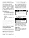
ADDITIONAL VENTING REQUIREMENTS
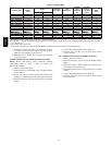
A 4--in. (102 mm) round vent elbow is supplied with the furnace.
A 5--in. (127 mm) or 6--in. (152 mm) vent connector may be
required for some model furnaces. A field--supplied 4--in. (102
mm) to 5--in. (127 mm) or 4--in. (102 mm) to 6--in. (152 mm)
sheet metal increaser fitting is required when 5--in. (127 mm) or
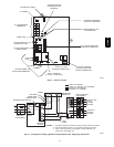
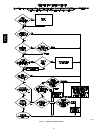
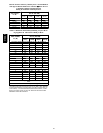
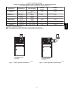
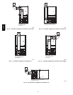
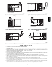
6--in. (152 mm) vent connector is used. See Fig. 28 -- 40 Venting
Orientation for approved vent configurations.
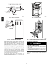
NOTE: Vent connector length for connector sizing starts at
furnace vent elbow. The 4--in. (102 mm) vent elbow is shipped
for upflow configuration and may be rotated for other positions.
Remove the 3 screws that secure vent elbow to furnace, rotate
furnace vent elbow to position desired, reinstall screws. The
factory--supplied vent elbow does NOT count as part of the
number of vent connector elbows.
The vent connector can exit the cabinet of the furnace through
one of 5 locations.
1. Attach the single wall vent connector to the furnace vent
elbow, and fasten the vent connector to the vent elbow
with at least two field--supplied, corrosion--resistant, sheet
metal screws located 180_ apart.
NOTE: An accessory flue extension is available to extend from
the furnace elbow to outside the furnace casing. See Table 17 for
accessory list. If flue extension is used, fasten the flue extension
to the vent elbow with at least two field--supplied,
corrosion--resistant, sheet metal screws located 180_ apart. Fasten
the vent connector to the flue extension with at least two
field--supplied, corrosion resistant sheet metal screws located
180_ apart.
2. Vent the furnace with the appropriate connector as shown
in Fig. 28 -- 40.
CUT HAZARD
Failure to follow this caution may result in personal injury.
Sheet metal parts may have sharp edges or burrs.
Use care and wear appropriate protective clothing, safety
glasses and gloves when handling parts and servicing
furnaces.
CAUTION
!
3. Determine the correct location of the knockout to be re-
moved.
4. Use a hammer and screwdriver to strike a sharp blow
between the tie points and work the slug back and forth
until the slug breaks free.
BURN HAZARD
Failure to follow this caution may cause personal injury.
Hot vent pipe is within reach of small children when
installed in downflow position.
See the following instruction.
CAUTION
!
An accessory Vent Guard Kit is REQUIRED for downflow
applications for use where the vent exits through the lower
portion of the furnace casing. Refer to the Vent Guard Kit
Instructions for complete details. See Table 17 for accessory list.
The horizontal portion of the venting system shall slope upwards
not less than 1/4--in. (6 mm) per linear ft. (21 mm/m) from the
furnace to the vent and shall be rigidly supported every 5 ft. (1.5
M) or less with metal hangers or straps to ensure there is no
movement after installation.
SIDEWALL VENTING
This furnace is not approved for direct sidewall horizontal
venting.
Per section 12.4.3 of the NFPA 54 / ANSI Z223.1--2009, any
listed mechanical venter may be used, when approved by the
authority having jurisdiction.
310AAV