


44
The control system also requires an earth ground for proper
operation of the control and flame--sensing electrode.
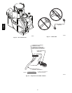
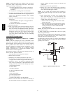
The 24--v circuit contains an automotive--type, 3--amp. fuse
located on the control. (See Fig. 25.) Any shorts of the 24--v
wiring during installation, service, or maintenance will cause this
fuse to blow. If fuse replacement is required, use ONLY a 3--amp.
fuse. The control LED will display status code 24 when fuse
needs to be replaced.
Proper instrumentation is required to service electrical controls.
The control in this furnace is equipped with a Status Code LED
(Light--Emitting Diode) to aid in installation, servicing, and
troubleshooting. It can be viewed through the sight glass in
blower access door. The furnace control LED is either ON
continuously, rapid flashing, or a code composed of 2 digits. The
first digit is the number of short flashes, the second digit is the
number of long flashes.
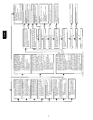
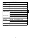
For an explanation of status codes, refer to service label located
on blower access door or Fig. 45 and the troubleshooting guide
which can be obtained from your distributor. The furnace control
will store 1 status code for 72 hrs.
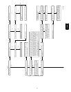
See Fig. 49, a brief Troubleshooting Guide.
1. To retrieve status code, proceed with the following:
NOTE: NO thermostat signal may be present at control, and all
blower--OFF delays must be completed.
a. Leave 115--v power to furnace turned on.
b. Remove outer access door.
c. Look into blower access door sight glass for current
LED status.
d. BRIEFLY remove insulated terminal wire from the
draft safeguard (DSS) switch until LED goes out (1 to
2 sec), then reconnect it.
2. When above items have been completed, the LED flashes
status code 4 times. Record this status code for further
troubleshooting.
3. Component self--test will begin. Refer to component
TEST section for complete test sequence.
4. Check LED status.
5. Refer to SERVICE label on front of the blower access
door for more information.
6. Check LED status. If no previous faults in history, control
will flash status code 11.
7. If LED status indicates proper operation, RELEASE
BLOWER ACCESS DOOR SWITCH, reattach wire to R
terminal on furnace control board, replace blower access
door, and replace burner access door.
Step 2 —Care and Maintenance
FIRE OR EXPLOSION HAZARD
Failure to follow this warning could result in personal
injury, death and/or property damage.
Never store anything on, near, or in contact with the
furnace, such as:
1. Spray or aerosol cans, rags, brooms, dust mops, vacuum
cleaners, or other cleaning tools.
2. Soap powders, bleaches, waxes or other cleaning
compounds, plastic or plastic containers, gasoline, kerosene,
cigarette lighter fluid, dry cleaning fluids, or other volatile
fluids.
3. Paint thinners and other painting compounds, paper bags,
or other paper products.
!
WARNING
For continuing high performance and to minimize possible
equipment failure, periodic maintenance must be performed on
this equipment. Consult your local dealer about proper frequency
of maintenance and the availability of a maintenance contract.
ELECTRICAL SHOCK AND FIRE HAZARD
Failure to follow this warning could result in personal
injury, death or property damage.
Turn off the gas and electrical supplies to the unit and install
lockout tag before performing any maintenance or service.
Follow the operating instructions on the label attached to
the furnace.
!
WARNING
CARBON MONOXIDE POISONING AND FIRE
HAZARD
Failure to follow this warning could result in personal
injury, death and/or property damage.
Never operate unit without a filter or with filter access door
removed.
!
WARNING
CUT HAZARD
Failure to follow this caution may result in personal injury.
Sheet metal parts may have sharp edges or burrs. Use care
and wear appropriate protective clothing, safety glasses and
gloves when handling parts and servicing furnaces.
CAUTION
!
The minimum maintenance on this furnace is as follows:
1. Check and clean air filter each month or more frequently if
required. Replace if torn.
2. Check blower motor and wheel for cleanliness each heating
and cooling season. Clean as necessary.
3. Check electrical connections for tightness and controls for
proper operation each heating season. Service as necessary.
4. Inspect burner compartment before each heating season for
rust, corrosion, soot or excessive dust. If necessary, have furnace
and burner serviced by a qualified service agency.
5. Inspect the vent pipe/vent system before each heating season
for rust, corrosion, water leakage, sagging pipes or broken
fittings. Have vent pipes/vent system serviced by a qualified
service agency.
6. Inspect any accessories attached to the furnace such as a
humidifier or electronic air cleaner. Perform any service or
maintenance to the accessories as recommended in the accessory
instructions.
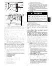
CLEANING AND/OR REPLACING AIR FIL
TER
The air filter arrangement will vary depending on the application.
The filter is exterior to the furnace casing.
NOTE: If the filter has an airflow direction arrow, the arrow
must point towards the blower.
310AAV