


Setting Up 1-1
1 —
2 —
3 —
4 —
5 —
6 —
7 —
8 —
?
!
9 —
CONTENTS
Index
Chapter 1 Setting Up
H
2
1
4
5
6
8
7
9
=
A
B
F
C
D
L
I
J
K
N
P
Q
R
T
V
W
X
S
G
M
O
U
E
3
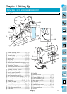
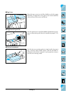
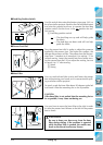
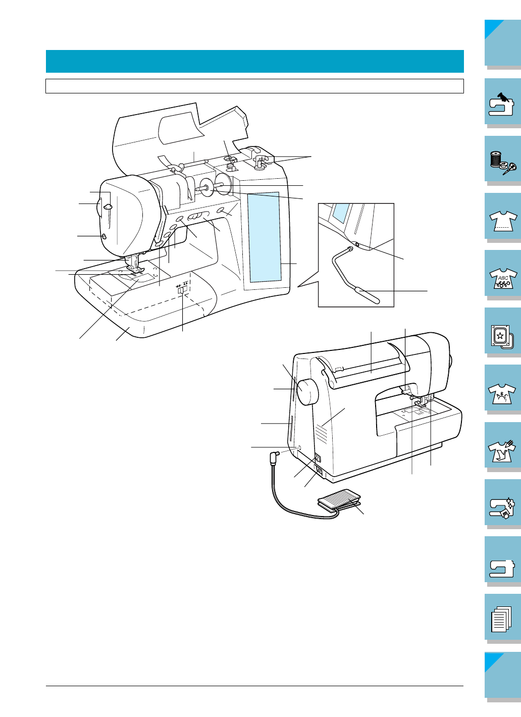
Principal Parts
PRINCIPAL PARTS AND THEIR OPERATION
1 Needle threader lever .............(P.1-35)
2 Presser foot dial ........................(P.1-6)
3 Thread cutter ............................(P.1-3)
4 Presser foot holder ........ (P.1-39, 1-42)
5 Presser foot ...............................(P.1-8)
6 Feed dogs .................................(P.1-6)
7 Bobbin cover ..........................(P.1-31)
8 Flat bed attachment with accessory com-
partment ............................(P.1-5, 1-8)
9 “Start/Stop” button ....................(P.1-3)
= “Reverse/Reinforcement Stitch” button
.................................................(P.1-3)
A “Needle Position” button ..........(P.1-3)
B “Thread Cutter” button..............(P.1-3)
C Sewing speed controller ............(P.1-4)
D “Bobbin Winder” button ...........(P.1-4)
E Feed dog position switch ..........(P.1-6)
F L.C.D. (liquid crystal display) ..(P.1-13)
G Spool cap...................... (P.1-25, 1-33)
H Spool pin ...................... (P.1-25, 1-33)
I Bobbin winder ........................(P.1-27)
J Thread guide for bobbin winding
...............................................(P.1-27)
K Supplemental spool pin ............ (P.1-5)
L Knee lifter mounting slot ...........(P.1-6)
M Knee lifter .................................(P.1-6)
N Handle
O Balance wheel ..........................(P.1-4)
P Embroidery card slot ...............(P.5-17)
Q Floppy disk drive slot ..............(P.5-18)
R Foot controller jack ...................(P.1-7)
S Main power switch .................(P.1-12)
T Cord jack ................................(P.1-12)
U Foot controller ..........................(P.1-7)
V Needle clamp screw ...............(P.1-44)
W Buttonhole lever .. (P.3-55, 3-58, 3-60)
X Presser foot lever.......................(P.1-4)
Y Air vent
Y