


Brute Magnum
Page 9
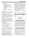
Term Description
Pipe Single-wall galvanized steel pipe, 24 gauge
minimum (sized per section 1.9)
Joint Permanent duct tape or aluminum tape
Sealing
Insulation Not required, but recommended R5 insulation
for cold installations (consult American Society
of Heating, Refrigerating, and Air Conditioning
Engineers (ASHRAE) handbook
Table 4. Required Combustion Air Piping Material.
In addition to air needed for combustion, air
shall also be supplied for ventilation, including all air
required for comfort and proper working conditions
for personnel. The Brute Magnum loses less than 1
percent of its input rating to the room, but other heat
sources may be present.
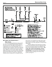
2.2 Venting
The Brute Magnum is a Category IV appliance
and must be installed with a stainless steel venting
system that complies with the UL 1738 Standard
(see Table 5). It must be installed per this installation
manual and the venting system manufacturer’s
Installation Instructions. The unit’s vent can terminate
through the roof, or through an outside wall. It can be
installed through walls that are from 3" (7.6cm) to 12"
(30cm) in thickness.
See Table 2 to select the appropriate vent pipe
diameter. The vent pipe must be pitch upward, toward
the vent terminal, so that condensate will run back to
the Brute Magnum, to drain. Route the vent pipe to
the heater as directly as possible. Seal all joints and
provide adequate hangers as required in the venting
system manufacturer’s Installation Instructions.
Horizontal portions of the venting system must be
supported to prevent sagging and may not have any
low sections that could trap condensate. The unit must
not support the weight of the vent pipe. Horizontal
runs must slope upwards not less than ¼ inch per
foot (21mm/m) from the unit to the vent terminal. Up
to five elbows can be used with the 50 feet (15.2m)
of pipe. Subtract 10 allowable linear feet for every
additional elbow used.
IMPORTANT NOTE ABOUT COMMON VENTING:
A single vent that is shared by multiple Brute Magnum
units MUST be engineered by a competent venting
specialist, and involves the selection of draft inducing
equipment, hardware and controls to properly
balance flue gas pressures. Do not common vent
Brute Magnum units unless the vent system
meets this requirement. Brute Magnum units are
never permitted to share a vent with Category I
appliances.
A condensate drain is built into the Brute
Magnum. A pressure switch monitors the condensate
drain pan, and will trip if the condensate level gets too
high. This will prevent the Brute Magnum from firing
if there is a blockage or overflow.
Connect a clear plastic tube, minimum 3/8"
diameter, between the drain connection and a floor
drain (or condensate pump if a floor drain is not
accessible).
Caution
Condensate is mildly acidic, and may harm some
floor drains and/or pipes, particularly those that
are metal. Ensure that the drain, drainpipe,
and anything that will come in contact with the
condensate can withstand the acidity, or neutralize
the condensate before disposal. Damage caused
by failure to install a neutralizer kit or to
adequately treat condensate will not be the
manufacturer’s responsibility.
A neutralizer kit is available from Bradford
White. The kit includes a condensate pump.
The condensate tray must be primed before starting
the unit. Fill the tray with water through the exhaust
vent connection on the back of the unit. Continue
filling until water flows out of the condensate drain
port. This prevents the flue gases from escaping through
the condensate drain. The condensate drain must be
installed so as to prevent accumulation of condensate.
When a condensate pump is not used, the tubing must
continuously slope downward (except for the trap loop)
toward the drain with no spiraling.
Consult local codes for disposal method.
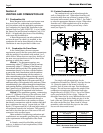
Term Description
Venting Sealed stainless steel
system certified to UL1738.
Insulation Not required, but recommended R5
insulation with protective cover for cold
installations (consult American Society of
Heating, Refrigerating, and Air Conditioning
Engineers (ASHRAE) handbook)
Table 5. Required Venting Material.
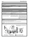
2.3 Locating Vent & Combustion Air
Terminals
2.3.1 Horizontal Vent Terminal
The appropriate side wall vent hood must be
used, and is listed in the installation and operation
manual. The terminal provides a means of installing
the vent piping through the building wall, and must
be located in accordance with ANSI Z223.1/NFPA 54
and applicable local codes. In Canada, the installation
must be in accordance with CSA B149.1 or .2 and
local applicable codes. Consider the following when
installing the terminal: