


BRADFORD WHITE CORP.
Page 40
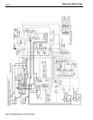
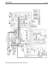
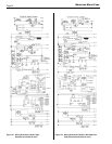
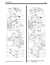
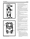
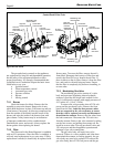
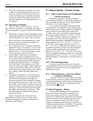
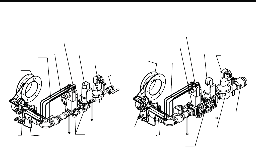
Figure 28. Gas Trains.
!
"
#
#
"
!
Control Pack B Gas Train
The gas and electric controls on the appliance
are engineered for long life and dependable operation,
but the safety of the equipment depends on their
proper functioning. It is strongly recommended that
a qualified service technician inspect the basic items
listed below every year.
a. Ignition control
b. Water temperature control
c. Automatic gas valve
d. Pressure switches
e. Blower
f. Mixing control
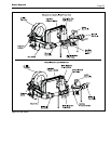
7.2.1 Burner
Check the burner for debris. Remove the fan
assembly to access the burner. Remove the 6 nuts,
which hold the burner in place. Pull burner up and out.
Clean burner, if necessary, by blowing compressed air
from the outside of the burner into the center of the
burner, and wipe the inside of the burner clean with
glass cleaner. A dirty burner may be an indication
of improper combustion or dirty combustion air.
Determine the cause, and correct. Always replace the
burner gasket when replacing the burner.
7.2.2 Filter
The filter used in the Brute Magnum is washable
with an 83% arrestance. Since the filter is washable, it
will only need replacement in very rare cases. If filter
replacement is needed, it should only be replaced with
factory parts. To access the filter, remove the unit’s
front panel. Disengage latch on top of filter box and
remove the filter box cover. Inspect the air filter. If
there is debris on the air filter, remove it from the filter
box, and wash it with mild soap and water. Ensure
that the filter is completely dry before re-installing, in
reverse order.
7.2.3 Modulating Gas Valve
The modulating gas valve consists of a valve
body and a pressure regulating electro-hydraulic
actuator. It provides the air/gas ratio control for the
unit. It is designed to operate with supply pressures of
4-13 inches w.c. (1.0 to 3.2 kPa).
To remove the valve actuator, shut off 120-volt
power and the gas shutoff valve. Remove the front
panel from the unit. Label the four pressure tubes
that are connected to the valve actuator, to ensure
that they will be replaced correctly and disconnect
them from the actuator. Remove the four tubes from
the barb connectors. Disconnect the 120-volt wires
from the actuator. Remove the valve actuator by taking
out the four screws, and pulling the actuator out. Re-
install in reverse order. Turn on gas shutoff valve and
120 volt power and check appliance operation and
tightness of gas valve connections.
The gas valve body will rarely have to be
removed. If there is a valve problem, and it has been
determined the actuator is working properly, the gas
valve body may need to be replaced. To remove the
gas valve body, shut off 120-volt power and the gas