


Brute Magnum
Page 13
At the time of removal of an existing boiler, the
following steps shall be followed with each appliance
remaining connected to the common venting system
placed in operation, while the other appliances
remaining connected to the common venting system are
not in operation.
1. Seal any unused openings in the common venting
system.
2. Visually inspect the venting system for proper
size and horizontal pitch and determine there is
no blockage or restriction, leakage, corrosion and
other deficiencies which could cause an unsafe
condition.
3. Insofar as it is practical, close all building doors
and windows and all doors between the space in
which the appliances remaining connected to the
common venting system are located and other
spaces of the building. Turn on clothes dryers
and any appliance not connected to the common
venting system. Turn on any exhaust fans, such
as range hoods and bathroom exhausts, so they
will operate at maximum speed. Do not operate a
summer exhaust fan. Close fireplace dampers.
4. Place in operation the appliance being inspected.
Follow the lighting instructions. Adjust thermostat
so appliance will operate continuously.
5. Test for spillage at the draft hood relief opening
after 5 minutes of main burner operation. Use
the flame of a match or candle, or smoke from a
cigarette, cigar or pipe.
6. After it has been determined that each appliance
remaining connected to the common venting
system properly vents when tested as outlined
above, return doors, windows, exhaust fans,
fireplace dampers and any other gas burning
appliance to their previous conditions of use.
7. Any improper operation of the common venting
system should be corrected so that the installation
conforms to the National Fuel Gas Code, ANSI
Z223.1/NFPA 54 and/or CSA B149.1, Installation
Codes. When resizing any portion of the common
venting system, the common venting system
should be resized to approach the minimum size
as determined using the appropriate tables
and guidelines in the National Fuel Gas Code,
ANSI Z223.1 NFPA 54 and/or CSA B149.1,
Installation Codes.
Section 3
GAS SUPPLY AND PIPING
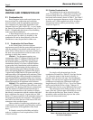
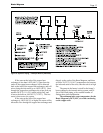
3.1 Gas Supply and Piping
Gas piping should be supported by suitable
hangers or floor stands, not the appliance.
Review the following instructions before
proceeding with the installation.
1. Verify that the appliance is fitted for the
proper type of gas by checking the rating plate.
Appliances are normally equipped to operate at
elevations up to 2000 feet (610m). However,
the appliance will function properly without the
use of high altitude modification at elevations
up to 10,000 feet (3050 m).
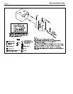
2. The maximum inlet gas pressure must not
exceed 13" W.C. (3.2kPa). The minimum
inlet natural gas pressure is 4" W.C. (1.0kPa)
and minimum inlet propane gas pressure is 6"
(1.5kPa).
3. Refer to Table 6, size supply.
4. Run gas supply line in accordance with all
applicable codes.
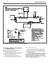
Note: If you have a boiler/water heater with
a normally open vent valve, install a vent line
from the vent valve to an outside location
as required by your installation code or IRI
requirement. Do not remove 3/4 inch pipe
plug from the vent valve if venting from the
normally open vent valve is not required by
your installation code.
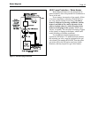
5. Locate and install manual shutoff valves in
accordance with state and local requirements.
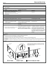
6. A sediment trap must be provided upstream of
the gas controls.
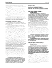
Size and
Distance from Gas Meter or Last Stage Regulator
Gas Type
0-50 feet 0-15m 50-100 feet 15-31m 100-200 feet 31-61m 200-300 feet 61-91m
1200 natural 2" 5.1cm 2-1/2" 6.4cm 2-1/2" 6.4cm 3" 7.6cm
1200 propane 1-1/2" 3.8cm 2" 5.1cm 2" 5.1cm 2-1/2" 6.4cm
1600 natural 2-1/2" 6.4cm 2-1/2" 6.4cm 3" 7.6cm 3" 7.6cm
1600 propane 2" 5.1cm 2" 5.1cm 2-1/2" 6.4cm 2-1/2" 6.4cm
2000 natural 3" 7.6cm 3" 7.6cm 3" 7.6cm 3-1/2" 8.9cm
2000 propane 2-1/2" 6.4cm 2-1/2" 6.4cm 2-1/2" 6.4cm 3" 7.6cm
2400 natural 2-1/2" 6.4cm 3" 7.6cm 3" 7.6cm 3-1/2" 8.9cm
2400 propane 2" 5.1cm 2-1/2" 6.4cm 2-1/2" 6.4cm 3" 7.6cm
Notes: 1. These figures are based on 1/2" 0.12kPa water column pressure drop.
2. Check supply pressure and local code requirements before proceeding with work.
3. Pipe fittings must be considered when determining gas pipe sizing.
Table 6. Gas Piping Sizes.