


Brute Magnum
Page 43
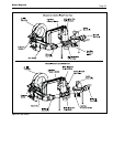
8. Clean the heat exchanger: A light accumulation
of soot or corrosion on the outside of the heat
exchanger can be easily removed. Use a wire
brush to remove loose soot and scale from the
heat exchanger. Do not use water or compressed
air for cleaning.
9. NOTE: While the heat exchanger is out of the
unit, inspect the firewall refractory insulation
blocks for cracks, wear and breakage. Replace if
necessary.
10. Inspect the inside of the copper tubes for scale
buildup. Scale can build up on the inner surface
of the heat exchanger tubes, which can restrict
water flow. If the tubes show signs of scaling,
clean the internal surface. Bradford White offers
a tube cleaning kit, part number R2000700.
11. Reassemble in the reverse order.
If heat exchanger removal is necessary, consult
the factory for instructions.
NOTE: The Warranty does not cover damage
caused by lack of required maintenance, lack of
water flow, or improper operating practices.
The condensing (stainless steel) heat exchanger
is not in the firing chamber, so it will not experience
sooting. If there is fouling on the stainless steel heat
exchanger, or if it needs to be changed, contact the
factory.
7.2.17 Normally Open Vent Valve
Some Brute Magnum models provide a
normally open vent valve for installations with IRI
code requirements. The valve opens when power is
removed from the safety valves. And the valve closes
when the safety valves are powered. See Section 3.1
item #4 for installation instructions.
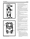
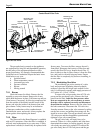
7.2.18 Motorized Safety Valve
Control packs B and E have an additional
motorized safety valve. This valve is powered open
at the same time as the safety valve. To remove the
valve actuator, shut off the 120V power and the gas
shutoff valve. Remove the right side, or front panel.
Disconnect the 120V wires from the actuator. Remove
the valve actuator by taking out the four screws, and
pulling the actuator out. Re-install in reverse order.
Turn on gas shutoff valve and 120V power and
check appliance operation and tightness of gas valve
connections.
The gas valve body will rarely have to be
removed. If there is a valve problem, and it has been
determined the actuator is working properly, the gas
valve body may need to be replaced. To remove the
gas valve body, shut off 120V power and the gas
shutoff valve. Remove the right side and front panels.
Remove the valve actuator. Unscrew the valve body
from the gas train. After the valve has been removed,
replace with a new valve in reverse order. Turn on gas
shutoff valve and 120V power and check appliance
operation and tightness of gas valve connections.
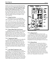
7.2.19 Gas Pressure Switches
The high and low gas pressure switches are 24V
manual reset switches that act to cut power to the gas
valves if the gas pressure is too low or too high for
proper operation. The gas pressure switches used are
integrally vent limited, and do not require venting to
atmosphere. To remove a switch, remove the screw
on the plastic housing and pull the clear cover off.
Disconnect the two wires from the screw terminals.
Twist the switch off the pipe nipple. Reassemble in
reverse order. For natural gas, set the low gas pressure
switch to 3" w.c. For propane, set the low gas pressure
switch to 5" w.c. For natural and propane, set the high
gas pressure switch to 14".
Section 8
TROUBLESHOOTING
8.1 Sequence of Operation
The Brute Magnum appliance is a cold start
appliance that should start only on a call for heat from
a tank aquastat, room thermostat, zone valve end
switch or other space temperature control device.
1. Upon a call for heat,
(a) The internal pump will start.
(b) The blower will begin a 15 second pre-
purge.
2. Following the prepurge cycle the hot surface
ignitor will heat and will begin a 7 second trial
for ignition. The unit is allowed three attempts
for ignition.
3. The gas valve will then be energized and low-
fire (50% of full fire) ignition will occur. The
unit will remain in a low-fire start-up period for 15
seconds.
4. After the low-fire start time is over, the unit
will be in normal operation firing rate and will
modulate based on the heating load via the
temperature controller settings and readings.
5. The mixing system control will sense the water
temperature entering the copper heat exchanger,
and will change the positions of the mixing
valves to divert enough hot water from the
copper heat exchanger outlet back to its inlet
to keep the inlet at a minimum 140°F (60°C).
Therefore, when the return water temperature is
140°F (60°C) or lower, the outlet temperature
will be 160-165°F (71-74°C). With return
temperatures greater than 140°F (60°C), the
temperature rise across the Brute Magnum is 20-
25°F (11-14°C), when the Brute Magnum is at
high firing rate.