


Brute Magnum
Page 7
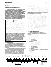
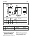
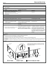
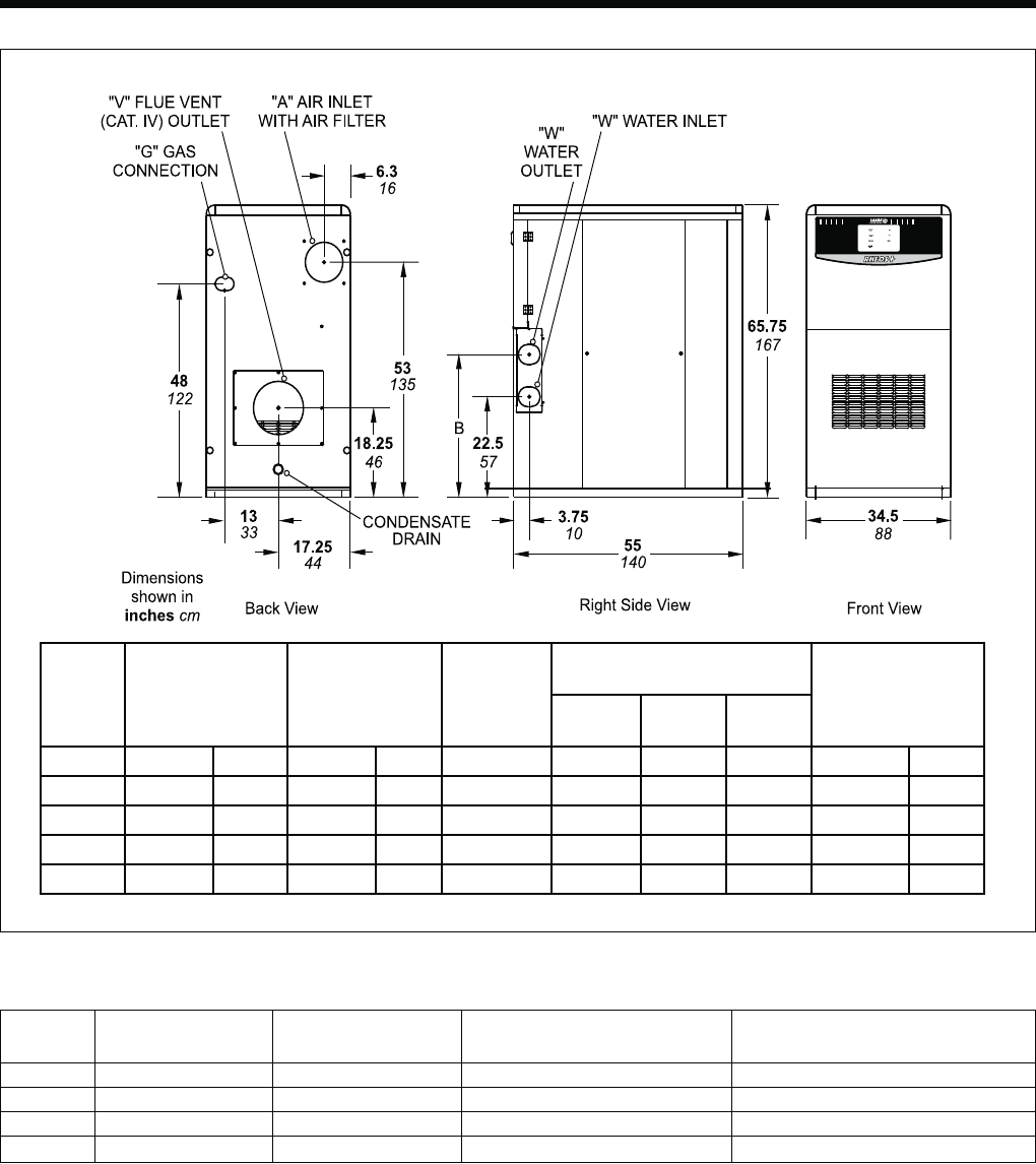
Figure 1. Dimensional Drawing.
Size Intake Exhaust Intake Exhaust
Size Size Maximum Run Maximum Run
1200 6" (15 cm) dia. 6" (15 cm) dia. 50 linear feet with 5 elbows 50 linear feet with 5 elbows
1600 8" (20 cm) dia. 6" (15 cm) dia. 50 linear feet with 5 elbows 50 linear feet with 5 elbows
2000 8" (20 cm) dia. 7" (18 cm) dia. 50 linear feet with 5 elbows 50 linear feet with 5 elbows
2400 8" (20 cm) dia. 10" (25 cm) dia. 50 linear feet with 5 elbows 50 linear feet with 5 elbows
Table 2. Vent / Air Pipe Sizes.
1.8 Locating Appliance for Correct Vent
Distance From Outside Wall or
Roof Termination
The forced draft combustion air blower in the
appliance has sufficient power to vent properly when
the guidelines in Table 2 are followed.
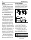
NOTE: When located on the same wall, the Brute
Magnum combustion air intake terminal must be
installed a minimum of 12" (30cm) below the exhaust
vent terminal and separated by a minimum of
36 inches (91cm) horizontally.
Size
“V”
Vent Outlet
Connection
“A”
Air Inlet
Connection
“W”
Water
Inlet/ Outlet
Connection
“G” Gas Connects.
Control Packages
“B”
Std & A
Nat/ LP
B & E
Nat
B & E
LP
inches inches NPT NPT NPT NPT inches
1200 6 6 2-1/2” 1’ 1-1/2’ 1-1/2” 34-1/4”
1600 6 8 2-1/2” 1-1/2’ 2” 2’ 34-1/4”
2000 7 8 3” 1-1/2’ 2” 2” 34-1/4”
2400 10 8 3” 1-1/2” 2” 2” 32”