


BRADFORD WHITE CORP.
Page 4
Table 1 Clearances ........................................................6
Table 2 Vent / Air Pipe Sizes ..........................................7
Table 3 Horizontal Vent and Air Terminals
for Indoor Installations .......................................8
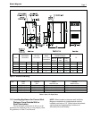
Figure 1 Dimensional Drawing ........................................7
Figure 2 Combustion Air and Vent Through Roof ............8
Figure 3 Combustion Air and Vent Through Side-Wall ..10
Figure 4 Hydronic Piping – Multiple Boilers ...................16
Figure 5 Hydronic Piping – Multiple Boilers (Alternate) .17
Figure 6 Hydronic Piping – One Boiler,
Multi-Temperature System ..............................18
Figure 7 Internal Piping Schematic................................19
Figure 8 Water Heater Piping – One Heater, One Tank ....20
Figure 9 Water Heater Piping – Multiple Heaters,
One Tank .........................................................21
Figure 10 Water Heater Piping – One Heater,
Multiple Tanks ..................................................22
Figure 11 Water Heater Piping – Multiple Heaters,
Multiple Tanks ..................................................23
Figure 12 Temperature Control........................................24
Figure 13 Proprotional Control ........................................25
Figure 14 Control Parameter Graph ................................26
Figure 15 Control Parameter Graph ................................27
Figure 16 Control Parameter Possible Interference ........28
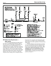
Figure 17 Wiring Diagram, Size 1200,
Standard and Codes A and F ..........................30
Figure 18 Wiring Diagram, Sizes 1600, 2000 and
2400, Standard and Codes A and F ................31
List of Tables
Table 4 Required Combustion Air Piping Material..........9
Table 5 Required Venting Material .................................9
Table 6 Gas Piping Sizes .............................................13
Table 7 Air & Gas Orifice Differentials at Full Fire ........38
List of Figures
Figure 19 Wiring Diagram Size 1200, Code B.................32
Figure 20 Wiring Diagram, Sizess 1600, 2000 and
2400, Code B ..................................................33
Figure 21 Wiring Schematic, Size 1200,
Standard and Codes A and F ..........................34
Figure 22 Wiring Schematic, Sizes 1600, 2000 and
2400, Standard and Codes A and F ................34
Figure 23 Wiring Schematic, Size 1200, Code B ............35
Figure 24 Wiring Schematic, Sizes 1600, 2000 and
2400, Code B ..................................................35
Figure 25 Gas/Air Test Panel ...........................................37
Figure 26 Test Panel Valves ............................................37
Figure 27 Gas Trains .......................................................39
Figure 28 Gas Trains .......................................................40
Figure 29 Control Panel...................................................41
Figure 30 Combustion Components ................................49
Figure 31 Gas Train/Combustion Air Components ..........50
Figure 32 Gas Train Components ...................................51
Figure 33 Electrical Components ....................................52
Figure 34 Heat Exchanger / Water Path Components ....53
Figure 35 Heat Exchanger / Water Path Components ....54
Figure 36 Jacket Components.........................................55