


BRADFORD WHITE CORP.
Page 42
7.2.10 Mixing Actuator
The mixing actuator connects to both mixing
valves and takes its signal from the mixing control
to properly set the valves to protect the copper heat
exchanger. To remove the actuator, remove the screw
on the front to take the cover off. Disconnect the wires.
Take the 2 nuts off the U-bolt, to move the linkage
to the side, out of the way. Slide the actuator out.
Reassemble in reverse order.
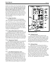
7.2.11 Ignition Control
The ignition control ensures the proved
interrupted-type ignition system. It controls the
hot surface ignitor and proves that the flame signal
is appropriate for powering the gas valves. It also
controls the blower’s pre-purge and post-purge. To
replace the control, shut off the 120-volt power to the
appliance. Remove the cover from the control panel.
Remove the electrical connectors from the ignition
control. Take out the controller’s mounting screws, and
pull the controller out. Replace in reverse order.
7.2.12 Ignitor / Flame Sensor Assembly
The ignitor is a 110v “hot surface” type. It
is energized whenever there is a call for heat and
switched off when ignition is established and the flame
has been sensed. Ignitors with an ohms resistance over
80 ohms (tested after the ignitor has been allowed
to cool to room temperature) should be replaced. To
replace the ignitor, shut off the 120-volt power to the
appliance, disconnect the Molex connector, remove
the two mounting screws on the ignitor flange, and
pull the ignitor out. Always install a new ignitor gasket
with the replacement ignitor.
Caution
Ignitor gets hot and can cause burns or injury.
7.2.13 Transformers
There are various transformers used on the Brute
Magnum units. Be sure to replace the transformers
with factory parts. These transformers are not capable
of supplying control voltage for external devices such
as zone valves, which must have their own separate
power supply. Should a transformer need replacing,
shut off the 120-volt power. Unplug the transformer
wires, remove the mounting screws and remove the
transformer. Replace transformer in the reverse order.
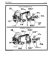
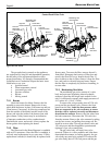
7.2.14 Blower
The combustion air blower is a high-pressure
centrifugal blower with a variable speed motor. The
speed of the motor is determined by the control logic,
and the 120-volt current remains on to the blower at all
times. If a blower change is required, turn off the 120-
volt power and gas supply to the unit. Take the front
panel, the two side access panels, and the top jacket
panel off. (If there is enough clearance on the side, the
top may not have to be removed.) Disconnect the gas
union between the blower and gas valves. Disconnect
the filter box assembly (at the air transition) from the
blower (six 8 mm bolts). Disconnect the two Molex
electrical connectors from the top right of the blower.
Remove the four nuts from the blower flange, and
pull the blower out. Replace blower in reverse order,
ensuring that all joints are made correctly and sealed.
After replacement, ensure that the unit operates
properly, by following the set-up procedure in this
manual.
7.2.15 Flow Switch
The Brute Magnum uses a paddle-type flow
switch to ensure that the unit has water flow before
ignition is allowed.
7.2.16 Heat Exchanger Coils
Black carbon soot buildup on the external
surfaces of the copper heat exchanger is caused by
one or more of the following; incomplete combustion,
combustion air problems, venting problems and heater
short cycling. Soot buildup or other debris on the heat
exchanger may restrict the flue passages.
If black carbon soot buildup on the copper
exchanger is suspected, disconnect electrical supply
to the unit, and turn off the gas supply by closing
the manual gas valve on the unit. Access the heat
exchanger through the side access panels, and inspect
the finned copper tubing using a flashlight. If there is
a buildup of black carbon soot or other debris on the
heat exchanger, clean per the following:
Caution
Black carbon soot buildup on a dirty heat exchanger
can be ignited by a random spark or flame. To
prevent this from happening, dampen the soot
deposits with a wet brush or fine water spray before
servicing the heat exchanger.
1. Disconnect the electrical supply to the unit.
2. Turn off the gas supply by closing the manual gas
valve on the heater.
3. Disconnect and remove the wires, conduit and
sensors from all components that are attached to
the inlet/outlet header.
4. Isolate the heat exchanger from the water supply.
5. Drain the heat exchanger from the drain located
on the bottom of the heat exchanger.
6. Disconnect the header flanges from the inlet and
outlet.
7. Remove the heat exchanger from the unit.
NOTE: The heat exchangers are heavy and may
require two people to remove to avoid personal
injury.