


BRADFORD WHITE CORP.
Page 8
2.1.2 Intake Combustion Air
The combustion air can be taken through the
wall, or through the roof. When taken from the wall,
it must be taken from out-of-doors by means of the
horizontal wall terminal, shown in Table 3. See Table 2
to select the appropriate diameter air pipe. When taken
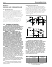
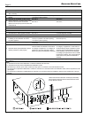
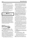
from the roof, a field-supplied rain cap or an elbow
arrangement must be used to prevent entry of rain
water (see Figure 2).
Section 2
VENTING AND COMBUSTION AIR
2.1 Combustion Air
Brute Magnum boilers and water heaters must
have provisions for combustion and ventilation
air in accordance with the applicable requirements
for Combustion Air Supply and Ventilation in the
National Fuel Gas Code, ANSI Z223 1; or in Canada,
the Natural Gas and Propane Installation Code, CSA
B149.1. All applicable provisions of local building
codes must also be adhered to.
A Brute Magnum unit can take combustion
air from the space in which it is installed, or the
combustion air can be ducted directly to the unit.
Ventilation air must be provided in either case.
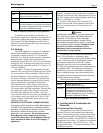
2.1.1 Combustion Air From Room
In the United States, the most common
requirements specify that the space shall communicate
with the outdoors in accordance with method 1 or 2,
which follow. Where ducts are used, they shall be of
the same cross-sectional area as the free area of the
openings to which they connect.
Method 1: Two permanent openings, one
commencing within 12" (300mm) of the top and one
commencing within 12" (300mm) of the bottom, of
the enclosure shall be provided. The openings shall
communicate directly, or by ducts, with the outdoors
or spaces that freely communicate with the outdoors.
When directly communicating with the outdoors, or
when communicating to the outdoors through vertical
ducts, each opening shall have a minimum free area of
1 square inch per 4000 Btu/hr (550 square mm/kW) of
total input rating of all equipment in the enclosure. When
communicating to the outdoors through horizontal ducts,
each opening shall have a minimum free area of not less
than 1 square inch per 2000 Btu/hr (1100 square mm/kW)
of total input rating of all equipment in the enclosure.
Method 2: One permanent opening, commencing
within 12" (300mm) of the top of the enclosure, shall
be permitted. The opening shall directly communicate
with the outdoors or shall communicate through a
vertical or horizontal duct to the outdoors or spaces
that directly communicate with the outdoors and shall
have a minimum free area of 1 square inch per 3000
Btu/hr (734 square mm/kW) of the total input rating of
all equipment located in the enclosure. This opening
must not be less than the sum of the areas of all vent
connectors in the confined space.
Other methods of introducing combustion and
ventilation air are acceptable, providing they conform
to the requirements in the applicable codes listed
above.
In Canada, consult local building and safety
codes or, in absence of such requirements, follow
CAN/CGA B149.
Figure 2. Combustion Air and Vent Through Roof.
Use single-wall galvanized pipe for the
combustion air intake (see Table 4), sized per Section
1.8. Route the intake to the heater as directly as
possible. Seal all joints with tape. Provide adequate
hangers. The unit must not support the weight of the
combustion air intake pipe. Maximum linear pipe
length allowed is 50 feet (15.2m). Up to five elbows
can be used with the 50 feet of pipe. Subtract 10
allowable linear feet for every additional elbow used.
The connection for the intake air pipe is in the
back of the unit. Take the plate off the back to reveal
the collar on the filter box. Run a bead of silicone
around the collar and slide the pipe over the collar.
Secure with sheet metal screws.
Size
Horizontal Combustion Horizontal Vent
Air Terminal Terminal
1200 20260701 D2004500
1600 20260703 D2004500
2000 20260703 D2004600
2400 20260703 D2006200
Table 3. Horizontal Vent and Air Terminals
for Indoor Installations.