


BRADFORD WHITE CORP.
Page 24
Section 5
ELECTRICAL CONNECTIONS
WARNING
The appliance must be electrically grounded in
accordance with the requirements of the authority
having jurisdiction or, in the absence of such
requirements, with the latest edition of the National
Electrical Code, ANSI/NFPA 70, in the U.S. and
with latest edition of CSA C22.1 Canadian Electrical
Code, Part 1, in Canada. Do not rely on the gas
or water piping to ground the metal parts of the
boiler. Plastic pipe or dielectric unions may isolate
the boiler electrically. Service and maintenance
personnel, who work on or around the boiler, may
be standing on wet floors and could be electrocuted
by an ungrounded boiler. Electrocution can result in
severe injury or death.
Single pole switches, including those of safety
controls and protective devices must not be wired in a
grounded line.
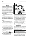
All electrical connections are made in the field
wiring box that is located inside the appliance.
NOTE: All internal electrical components have been
prewired. No attempt should be made to connect
electrical wires to any other location except the wiring
box.
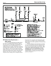
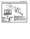
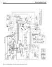
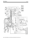
Wiring connections are shown in Figures 17
through 24.
5.1 Main Power
Connect a properly sized and fused, 120-volt
supply to the main power switch (hot leg is connected
directly to switch). Neutral leg is connected directly to
the white wire. Ground wire can be connected to the
grounding screw in the box or on the switch.
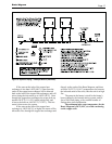
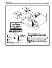
5.2 Pump Connections
The pump time delay relay will call the pump
to be energized upon a call for heat, and will keep the
pump energized for a delay period after the call for
heat has ended. The delay period is adjustable from
0.1 to 10 minutes.
Brute Magnum units have pumps that are wired
at the factory to the pump time delay system. It is
necessary to wire the pump to a separate 115V or
230V single phase circuit, per the wiring diagrams in
Figures 17 through 20.
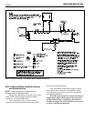
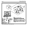
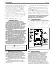
5.3 Temperature Control — Boiler
Connect boiler field interlock wires to isolated
contacts on zone valves, circulator relays, sequencing
controls (multiple boiler applications) or other
temperature controlling devices.
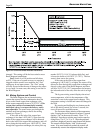
The Brute Magnum temperature control
measures temperature on the boiler inlet, sensing
return water temperature. Set the temperature control
for the desired return temperature. If the return water
temperature is less than 140°F (60°C), internal mixing
will keep the outlet temperature at 160-165°F (71-
74°C). If the return temperature is 140°F (60°C) or
higher, the outlet temperature of the boiler will be the
return temperature plus 20-25°F (11-14°C) when the
Brute Magnum is at high firing rate.
The manual reset high limit is on the outlet of
the Brute Magnum. Set the manual reset high limit at
about 20°F (11°C) higher than the highest expected
outlet temperature, to avoid nuisance lockouts.
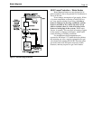
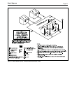
5.4 Temperature Control – Water Heater
5.4.1 Remote Water Heater
Temperature Control
The Brute Magnum water heater can be used
with a field-supplied tank aquastat, sequencing control,
or other temperature control device, which will call
the unit for heat when the temperature goes below the
controller’s setpoint. For the most efficient setting, set
the tank temperature at the lowest possible setting for
adequate hot water in the application.
Caution
If the tank temperature control is set too high, a
potential for hot water scalding may exist.
After a setting has been chosen for the tank
temperature control, set the heater temperature control
10°F (6°C) higher. The Brute Magnum temperature
control measures temperature on the heater inlet,
sensing return water temperature. If the return water
Figure 12. Temperature Control.