


Brute Magnum
Page 29
The second menu “Add” has to do with the N2
address. Pressing enter when “Add” is displayed will
display “255”, which stands for 255 unique addresses.
The up and down arrows change this value, and enter
saves the value if it is changed.
Changing the “Add” value will have no affect
on the Brute Magnum, unless a communications
card as been built onto the unit. If a Brute
Magnum unit has been ordered with an optional
communications card, more menus will be active,
and the unit will come with separate instructions.
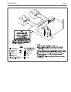
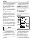
5.7 External Control Connections
Brute Magnum units are built with a selector
switch and a terminal strip to allow the Brute Magnum
to receive a 0-10VDC signal from an
external controller (such as a building automation
system or multiple boiler control).
When the selector switch is in the “Brute
Magnum Control” position, the Brute Magnum will be
modulated by the unit’s factory-mounted modulating
control.
When the switch is in the “External Control”
position, the unit look for a 0-10VDC signal from an
external (field-supplied) controller.
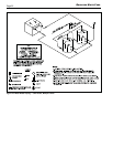
To interlock the external boiler control with
the Brute Magnum, the call for heat signal MUST
be connected to the field interlock terminal strip on
the Brute Magnum (shown in Figure 29). Be sure to
remove the factory-installed jumper between the field
interlock terminals. The 0-10VDC modulating signal
MUST be connected to external control terminal strip,
located to the right of, and behind the front panel. The
terminal strip is labeled “0-10VDC +” and 0-10VDC
–” to indicate which terminal received the hot signal
(+) and which terminal receives the common signal (-)
from the controller.
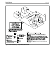
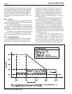
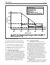
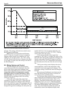
The Brute Magnum unit will modulate between
2.23V and 10V (for 25% and 100%, respectively).
Anything less than 2.23 volts will result in 25% of full
fire.
For the external control to modulate the Brute
Magnum, the selector switch on the front panel must
be in the “External Control” position.
Important Note: DO NOT MAKE/BREAK Brute
Magnum LINE VOLTAGE TO SIGNAL CALL FOR
HEAT. A “call for heat / end call for heat” MUST be
connected to the field interlock terminals. The Brute
Magnum does not recognize 0 volts as a signal to shut
off. If the call for heat is not connected between the
field interlock terminals, the Brute Magnum will remain
in low fire when it sees 0 volts as a modulating signal.
Caution
Brute Magnum supply voltage must not be
disengaged, except for service or isolation, or
unless otherwise instructed by procedures outlined
in this manual. To signal a call for heat, use the 24V
field-interlock, as shown in the wiring diagram(s).
Some Brute Magnum components are designed
to have constant voltage during normal operation.
If Brute Magnum supply voltage is toggled as a
call for heat signal, premature failure of these
components may result.
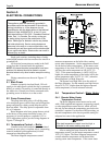
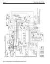
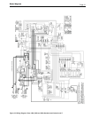
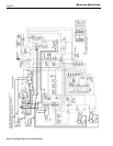
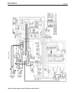
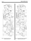
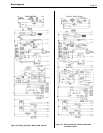
5.8 Wiring Diagrams
Caution
Label all wires prior to disconnection when servicing controls. Wiring errors can cause improper and dangerous
operation. Verify proper operation after servicing.