


6
SECTION III: GENERAL INFORMATION
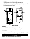
FEATURES
1. Porcelain enamel lined tank provides corrosion protection with a tough glass lining on the interior of the tank.
2. Magnesium anodes provide an extra measure of protection and extends tank life.
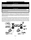
3. Direct Vent design with an induced draft blower. Flue gases are exhausted and combustion air is taken from outside
the building through 3” or 4” PVC, CPVC, or ABS pipe. Maximum venting distance for each pipe of 40 feet with one
elbow for 3” diameter pipe and 55 feet with one elbow for 4” diameter pipe. May be horizontally or vertically vented.
See venting section for complete details.
4. Hand Hole Cleanout allows inspection of tank interior and allows the removal of lime and sediment deposits.
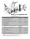
5. Honeywell Integrated Water Heater has the following features:
Attractive digital water heater display on control panel for precisely setting and displaying the temperature setpoint.
Pressing temperature up and down buttons changes the temperature setpoint. Temperature format may be
displayed in degrees F or degrees C.
Single control board with plug in wiring controls temperature, ignition, and induced draft blower operation.
Reduced number of parts for servicing and wiring.
Plug in wiring reduces chance of miswiring.
Water heater display will show diagnostic codes in the event the water heater needs servicing. Aids in diagnosing
and servicing the water heater. Temperature of the tank sensors can be monitored in the Service Mode.
Water heater display can show up to 10 previous error codes to further aid in servicing the water heater.
Keep clear of combination temperature and pressure relief valve discharge line outlet. The discharge may be
hot enough to cause scald injury. The water is under pressure and may splash.
For protection against excessive temperatures and pressure, install temperature and pressure protective equipment
required by local codes, but not less than a combination temperature and pressure relief valve certified by a
nationally recognized testing laboratory that maintains periodic inspection of production of listed equipment or
materials as meeting the requirements of the Standard for Relief Valves and Automatic Gas Shutoff Devices for Hot
Water Supply Systems, ANS Z21.22 and the Standard CAN1-4.4 Temperature, Pressure, Temperature and
Pressure Relief Valves and Vacuum Relief Valves. The combination temperature and pressure relief valve must be
marked with a maximum set pressure not to exceed the maximum working pressure of the water heater. The
combination temperature and pressure relief valve must also have an hourly rated temperature steam BTU
discharge capacity not less than the hourly rating of the water heater.
Install the combination temperature and pressure relief valve into the opening provided and marked for this purpose
on the water heater.
Note: Some models may already be equipped or supplied with a combination temperature and pressure relief valve.
Verify that the combination temperature and pressure relief valve complies with local codes. If the combination
temperature and pressure relief valve does not comply with local codes, replace it with one that does. Follow the
installation instructions above on this page.
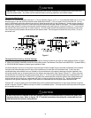
Install a discharge line so that water discharged from the combination temperature and pressure relief valve will exit
within six (6) inches (15.2 cm) above, or any distance below the structural floor and cannot contact any live electrical
part. The discharge line is to be installed to allow for complete drainage of both the combination temperature and
pressure relief valve and the discharge line. The discharge opening must not be subjected to blockage or freezing.
DO NOT thread, plug or cap the discharge line. It is recommended that a minimum clearance of four (4) inches
(10.2 cm) be provided on the side of the water heater for servicing and maintenance of the combination temperature
and pressure relief valve.
Do not place a valve between the combination temperature and pressure relief valve and the tank.
WARNING