


16
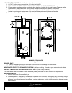
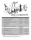
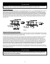
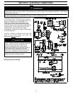
Through the Wall Venting:
Cut two 3 1/2” (8.9 cm) diameter holes (for 3” (7.6 cm) diameter pipe) or 4 1/2” (11.4 cm) diameter holes (for 4” (10.2 cm)
diameter pipe) in the wall with the centerline hole distances at least 6” (15.2 cm) apart, but not more than 24” (61 cm)
apart in the location where the exhaust vent and air intake terminals will exit the outside wall. Use the proper cement to
secure the 90° exhaust vent and air intake terminals provided with the water heater to the pipes. The distance between
the back edge of the 90° exhaust vent terminal and the exterior wall (see Figure 5) must be 5 inches (12.7 cm) more for
the exhaust vent terminal than the air intake terminal. Use the proper cement and assembly procedures to secure the
vent connector joints between the terminal and the blower outlet. Provide support brackets for every 3 feet (.91 m) of
horizontal vent.
Figure 5
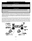
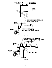
Through the Roof Venting: (Vertical Venting)
Cut the necessary holes through the roof and ceiling and install the exhaust vent and air intake pipes as shown in Figure
6. Make sure that the installation meets the local codes and/or The National Fuel Gas Code ANSI Z223.1 (Latest Edition)
or CGA/CAN B149 Propane or Natural gas Installation Code.
All vertical exhaust vent runs or horizontal runs more than 15 feet in length may accumulate condensate in the exhaust
vent pipe and exhaust blower and will require the installation of a drain tee and condensate trap. A drain tee and
condensate trap are available from your installer or the manufacturer of the water heater and must be installed in the
horizontal exhaust vent as close as practical to the blower vent connection (See Figures 7B and 7C). When using the
condensate tee, the exhaust vent piping must slope with a ¼” (6.35 mm) per foot pitch toward the condensate tee. For
short horizontal runs (less than 15 feet (4.57 m)) without the condensate tee, slope the exhaust vent piping toward the
outside vent terminal so that any condensate will drain out the vent terminal (see figure 7A). Venting arrangements
required for low ground clearance (figure 8) will require a condensate tee with the pipe sloped toward the tee.
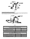
Connect 3/8” (15.9 mm) tubing from the barbed fitting on the condensate tee and form a loop using wire ties or tape as
shown in figures 7B and 7C before running to a drain or condensate pump. The loop forms a drain trap so that flue gases
do not escape into the room.
A drain loop must be installed in the drain tubing to serve as a condensate trap to prevent flue gases from
escaping into the room. Refer to figures 7B, 7C, and the instructions discussing the condensate drain tee
and trap under the vertical venting section.
CAUTION
IMPORTANT - All of the Exhaust Venting connections must be leak checked with a soap solution upon initial start
up of the water heater. Any leaks must be repaired before continuing operation of the water heater.
CAUTION