


10
LOCATE WATER HEATER in front of final position before removing crate.
1. LOCATE so that venting connections will be short and direct.
2. THIS WATER HEATER IS SUITABLE FOR INSTALLATION ON COMBUSTIBLE FLOOR.
3. Proper venting practices must be considered when selecting a location for this water heater. For exact venting
specifications, please consult the Venting section of these Installation and Operating Instructions.
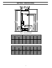
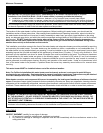
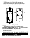
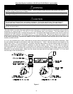
4. It is recommended that a minimum clearance of four (4) inches (10.2 cm) be provided on the side of the water
heater for servicing and maintenance of the combination temperature and pressure relief valve.
5. Increase distances to provide clearance for servicing.
MINIMUM CLEARANCES
Figure 2
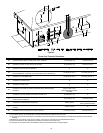
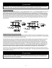
REMOVE CRATE
1. Remove all banding and pry off crate sides carefully so as not to damage the water heater.
2. Carefully roll/lift the water heater from the crate base.
MOVE WATER HEATER TO PERMANENT POSITION by sliding or walking. Place drain pan underneath water heater
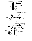
INSTALL TEMPERATURE AND PRESSURE RELIEF VALVE (if not already installed).
This water heater must be located in an area where the general public does not have access to set temperatures.
AIR REQUIREMENTS
1. Do not obstruct the flow of ventilating air.
2. For safe operation, adequate air is needed for combustion and ventilation. Sooting may result in serious damage
to the water heater and risk of fire or explosion. It can also create a risk of asphyxiation. Such a condition often
will result in a yellow, luminous burner flame, causing carboning or sooting of the combustion chamber, burner
and flue tubes.
IMPORTANT-The flow of combustion and ventilating air must not be obstructed.
WARNING