


37
SECTION XI: DIAGNOSTIC AND TROUBLESHOOTING GUIDE
DIAGNOSTIC GUIDE FOR HONEYWELL INTEGRATED CONTROL SYSTEM
SEQUENCE OF OPERATION FOR PDV AND INDUCED DRAFT MODELS
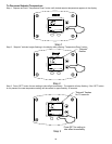
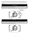
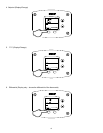
1. When the tank temperature drops below the temperature setpoint on the display, the control sends power to the
induced draft blower to start the ignition sequence.
2. When blower reaches the full operating speed, the pressure switch closes, completing the 24 volt circuit to the
safety circuit of the control. If the exhaust vent becomes blocked or the blower fails, the pressure switch will
open, the gas valves close, and the blower stops after a 5 second post-purge. The blower will restart and
continue to operate in the lockout condition until the blockage is removed or the venting problem is corrected.
Error code 29 will appear on the water heater display.
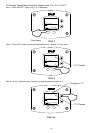
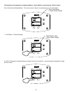
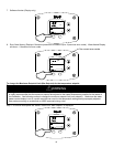
3. The control will continue to operate the blower for 15 seconds to “prepurge” any flue products remaining before
starting the ignition sequence.
4. After the prepurge period, the control sends 24 volt power to the pilot valve “PV” terminals on the gas valve
allowing pilot gas to flow to the pilot. The control also sends high voltage through the pilot electrode to spark to
the pilot hood and ignite the pilot gas. If the pilot does not ignite within 90 seconds, the pilot valve is denergized
and the sparking stops for 75 seconds. The control will attempt to ignite the pilot two more times. If the pilot does
not light on the 3
rd
attempt, the control will go into “soft lockout” for 1 hour and then will repeat the 3 ignition
attempts. The blower is off during the “soft lockout” period.
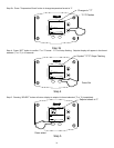
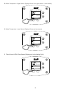
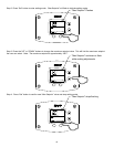
5. When the pilot is lit, the flame is sensed by the flame sense rod. The flame sense signal received by the control
board causes the sparking to stop and the main gas valve to open. The main burners ignite from the pilot flame.
The pilot is continually monitored by the flame sensing circuit. If for any reason, the pilot flame is not sensed by
the flame sensing circuit, the gas valves close. After a 75 second delay, the pilot valve opens and the pilot
electrode sparks to relight the pilot. The same sequence will occur in the event of a power supply or gas supply
interruption.
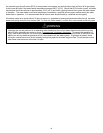
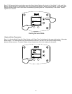
6. The main burners continue to operate until the water temperature in the tank increases past the control setpoint,
which will cause the gas valve to close. The blower stops operating 5 seconds after the gas valve closes. The
water heater remains in the standby mode until the temperature drops below the setpoint and initiates another
heating cycle.
7. If for some reason, the tank temperature should reach or exceed 200˚F, then the control closes the gas valve and
goes into a “hard lockout” state and will not operate until reset by a qualified service person. The display will read
“error code 65”, which indicates the tank high limit temperature has been exceeded. No attempt should be made
to reset the control until a service person has corrected the cause of the high limit condition. Refer to the
diagnostic service section at the end of this Installation and Operating Instructions Manual.