


14
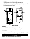
The vent system must terminate so that proper clearances are maintained as cited in local codes or the latest edition of
the National Fuel Gas Code, ANSI Z223.1.73.4e and 7.8a, b as follows:
1. Do not terminate near soffit vents or crawl space or other area where condensate or vapor could create a nuisance or
hazard or cause property damage.
2. Do not terminate the exhaust vent terminal where condensate or vapor could cause damage or could be detrimental
to the operation of regulators, relief valves, or other equipment.
3. Do not terminate the exhaust vent terminal over public area or walkways where condensate or vapor can cause
nuisance or hazard.
4. The vent must terminate a minimum of 12 inches above expected snowfall level to prevent blockage of vent
termination.
Vent pipes serving power vented appliances are classified by building codes as “vent connectors”. Required clearances
from combustible materials must be provided in accordance with information in this manual under LOCATION OF
WATER HEATER and CLEARANCES, and with National Fuel Gas Code and local codes.
All vent pipes and terminals are to have a 1” minimum clearance to combustibles. DO NOT use the placement of
insulation or other materials in the required clearance spaces surrounding the venting to combustible material unless
otherwise specified.
Note: Provide protection of the building materials from degradation by flue gases from the exhaust vent terminal.
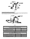
Horizontal And Vertical Direct Vent Lengths for 199,999 and 150,000 Btu/hr. Input Models
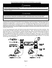
Reference the Venting Component Tables listed in the Installation (Direct Vent System Installation) for the maximum vent
lengths using 3” (7.6 cm) diameter piping. If longer venting distances are required than shown for 3” (7.6 cm) diameter
pipe, then 4” (10.2 cm) diameter pipe may be used. The distances shown in the tables are for each separate pipe (air
intake and exhaust vent).
Do not exceed the maximum allowed exhaust vent or combustion air pipe distances for the number of elbows
listed. Refer to the venting distances listed in tables 1-4 in this installation and operating instruction manual.
Note: The supplied exhaust vent and combustion air intake terminals may be used to vent through outside walls
of any thickness as long as the maximum allowed venting distances are not exceeded.
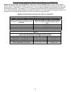
Maximum Venting Distances
(Horizontal, Vertical, or Combined for models under 200,000 Btu/hr. input ratings only)
TABLE 1 – EXHAUST VENT AND COMBUSTION AIR INTAKE PIPE LENGTHS FOR 3” (7.6 cm) PIPE
Number of 90° Elbows (Excluding vent terminals) Maximum distance of straight pipe (excluding
vent terminal) to exterior wall or roof.
1 40 ft. (12.19 m)
2 35 ft. (10.67 m)
3 30 ft. (9.14 m)
4 25 ft. (7.62 m)
TABLE 2 – EXHAUST VENT AND COMBUSTION AIR INTAKE PIPE LENGTHS FOR 4” (10.2 cm) PIPE
(For distances longer than 3” (7.6 cm) PIPE)
Number of 90° Elbows (Excluding vent terminals) Maximum distance of straight pipe (excluding
vent terminal) to exterior wall or roof.
1 55 ft. (16.8 m)
2 50 ft. (15.2 m)
3 45 ft. (13.7 m)
4 40 ft. (12.2 m)
Note: Each 90° elbow reduces the maximum venting distance by 5 ft. (1.52 m). Two 45° elbows are equal to one
90° elbow. Do not use 4” (10.2 cm) diameter pipe for venting distances less than 40 ft. (12.19 m) (with 1 elbow).
Use 3” (7.6 cm) pipe for venting distances of 40ft. (12.19 m) or less.
The total combined distances of vertical and horizontal pipe with equivalent elbow lengths cannot exceed the
maximum distance of straight pipe listed in the tables 1-4.
IMPORTANT - Do not exceed the venting distances or the number of elbows listed. Exceeding the maximum
venting distances may cause the water heater to malfunction or cause an unsafe condition.
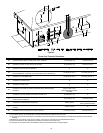
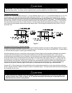
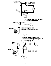
The exhaust vent adaptor and gasket with mounting bolts are located inside the cardboard carton with the vent
terminal. The exhaust vent adaptor and gasket must be installed on the blower outlet flange before attempting to
connect the 3” (7.6 cm) diameter vent pipe to the water heater.
NOTICE