


19
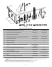
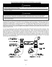
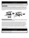
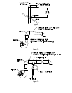
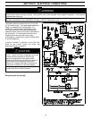
Direct Vent System Installation for Models with Input Ratings Over 200,000 Btu/Hr.
Models with input ratings over 200,000 Btu/hr. must use 4” (10.2 cm) diameter pipe. Install the blower adaptor
exhaust vent assembly and gasket supplied in the vent kit carton on the exhaust blower outlet flange as described in the
previous section. Connect the 4” (10.2 cm) pipe to the 4” (10.2 cm) reducers attached to the combustion air intake pipe
and blower exhaust outlet. The supplied 4” (10.2 cm) exhaust vent and combustion air intake terminals must also be
used. Follow the venting system installation instructions for installing 4” (10.2 cm) diameter pipe detailed on pages 14-17
and figures 4-8 and follow the venting tables 5 and 6 for the maximum venting distances.
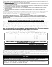
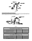
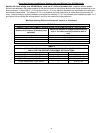
Maximum Venting Distances (Horizontal, Vertical, or Combined)
TABLE 5
EXHAUST VENT OR COMBUSTION AIR INTAKE PIPE LENGTHS FOR 4” (10.2 cm) PIPE
Number of 90° Elbows (Excluding vent
terminals)
Maximum distance of straight pipe (excluding
vent or air intake terminal) to exterior wall or
roof.
1 55 ft. (16.8 m)
2 50 ft. (15.2 m)
3 45 ft. (13.7 m)
4 40 ft. (12.2 m)
TABLE 6
4” (10.2 cm) EXHAUST VENT OR COMBUSTION AIR INTAKE PIPE LENGTHS FROM INSIDE
WALL FOR LOW GROUND CLEARANCE INSTALLATIONS
Terminating # of Elbows Maximum Length
(2) 90 Elbows with (1) 90 Elbow
1 45 ft (13.7 m)
(2) 90 Elbows with (1) 90 Elbow
2 40 ft (12.2 m)
(2) 90 Elbows with (1) 90 Elbow
3 35 ft (10.7 m)
(2) 90 Elbows with (1) 90 Elbow
4 30 ft (9.1 m)