


15
Direct Vent System Installation (199,999 and 150,000 Btu/hr. input models)
This water heater is a power direct vent appliance and is designed to vent both its products of combustion and provide the
combustion air supply through 3” (7.6 cm) or 4” (10.2 cm) diameter pipe to the outdoors. This water heater may be
vented either through the wall or vertically through the roof. The blower outlet adaptor provided in the vent kit carton and
combustion air inlet connection are designed to fit 3” (7.6 cm) diameter pipe. Remove the exhaust vent adaptor and
gasket from the vent kit carton. Line up the gasket screw clearance holes with the vent adaptor flange and place on top
of the blower outlet flange. Assemble the adaptor with the gasket to the blower outlet using the four (4) nuts, bolts, and
washers provided in the kit.
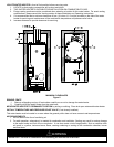
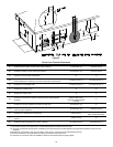
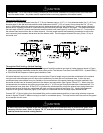
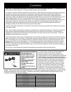
If 4” (10.2 cm) diameter pipe is used, a bell reducer must be used at the blower outlet and air intake connections. Seal
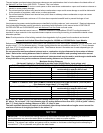
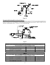
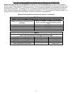
the joint between the pipe and the blower outlet collar (See figure 4). Table 1 lists the maximum vent lengths for this
water heater using 3” (7.6 cm) diameter pipe. If possible, locate the water heater so that the venting length and number of
elbows are kept to the minimum distance necessary to reach the outside. Use the 3” (7.6 cm) vent and intake air
terminals supplied with the water heater to terminate on the outside of the building. When using 4” (10.2 cm) diameter
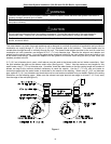
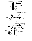
pipe, optional 4” (10.2 cm) diameter vent terminals must be used and are available from your dealer. Refer to the venting
illustrations on the following pages. Make sure the exhaust vent pipe terminal rear edge is at least 6” (15.2 cm) away
from the edge of the wall (see figure 5).
Figure 4
The direct vent system must be properly installed. Failure to properly install the direct vent system could result in
property damage, personal injury or death.
The water heater requires its own separate venting system. Do not connect the exhaust vent into an existing
vent
p
i
p
e or chimne
y
.
WARNING
Do not install any damaged direct vent system components. Contact the manufacturer of the water heater for
replacement parts. Use only the vent terminals provided or factory authorized for venting this water heater.
The flow of combustion air must not be restricted. Keep the direct vent terminal openings clear of objects,
shrubs, snow and debris.
CAUTION