


35
To reinstall the burner rack, reverse the above procedure.
Alternate method for removing the burner rack, when there is at least 20” (50.8 cm) clearance on the left front
side:
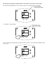
a) Shut off the gas and electrical supply to the water heater.
b) Disconnect both pilot tube fittings at the combustion box bulkhead fitting.
c) Disconnect wires to gas valve. Open control box and disconnect pilot spark and flame sense wires.
d) Disconnect the gas pipe union either above or below the gas valve.
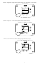
e) Remove the three screws securing the gasketed manifold flange on the left side of the combustion box.
f) Remove the burner access panel from the front of the combustion box.
g) Carefully remove and push the pilot wire grommet into the combustion box with the pilot wires.
h) Remove the four screws securing the manifold to the burner rack.
i) Carefully remove the manifold through the left side opening in the combustion box.
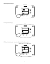
j) Remove the screw securing the curved burner shroud on the top center securing the burner assembly to the tank
skirt.
k) Slide out the burner rack assembly.
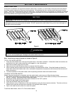
l) To remove the individual burners from the rack, the burner assembly shroud assembly must be removed from the
burner rack by removing the four (4) screws securing the shroud to the rack. The shroud must be reattached
to the burner rack after reinstalling the burners back in the rack.
To reinstall the burner rack, reverse the above procedure.
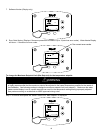
8. At least once a year, check the combination temperature and pressure relief valve to insure that the valve has not
become encrusted with lime.
Lift the lever at the top of the valve several times until the valve seats properly without leaking and operates freely.
9. Monthly drain off a gallon of water to remove silt and sediment.
10. If the combination temperature and pressure relief valve on the appliance discharges periodically, this may be due to
thermal expansion in a closed water supply system. Contact the water supplier or local plumbing inspector on how to
correct this situation. Do not plug the combination temperature and pressure relief valve outlet.
11. All models are equipped with a cleanout opening to aid in removal of hard water deposits from the tank bottom. If this
water heater operates under hard water conditions, the following should be performed at least every 3 months: Drain
the water heater. Remove the cleanout jacket cover and tank cover. When cleaning the tank, care must be taken to
avoid trying to break deposits loose as this could damage the glass lining and shorten the life of the water heater.
After cleaning, replace the cleanout tank cover and jacket cover, and refill with water. Refer to the section, “General
Operation” in this Installation and Operating Instruction manual for the procedures for filling and draining the water
heater.
12. Four sacrificial anode rods have been installed in the tank head to extend tank life. The anode rods should be
inspected annually for corrosion and replaced when necessary to prolong tank life. Water conditions in your area will
influence the time interval for inspection and replacement of the anode rod. The use of a water softener may increase
the speed of anode consumption. More frequent inspection of the anode is needed when using softened (or
phosphate treated) water. Contact the plumbing professional who installed the water heater or the manufacturer
listed on the rating plate for anode replacement information.
When lifting lever of the combination temperature and pressure relief valve, hot water will be released under
pressure. Be careful that any released water does not result in bodily injury or property damage.
Keep clear of the combination temperature and pressure relief valve discharge line outlet. The discharge
may be hot enough to cause scald injury. The water is under pressure and may splash.
WARNING
THIS WATER MAY BE HOT!
WARNING