


21
This water heater can deliver scalding temperature
water at any faucet in the system. Be careful
whenever using hot water to avoid scalding injury.
Certain appliances such as dishwashers and automatic
clothes washers may require increased temperature
water. By setting the thermostat on this water heater to
obtain the increased temperature water required by
these appliances, you may create the potential for
scald injury. To protect against injury, you should
install an ASSE approved mixing valve in the water
system. This valve will reduce point of discharge
temperature by mixing cold and hot water in branch
supply lines. Such valves are available from the
manufacturer of this water heater or a local plumbing
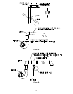
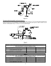
supplier. Please consult with a plumbing professional. For information regarding space-heating water connections and
plumbing arrangements, refer to the section, “Installation Instructions for Potable Water and Space Heating” in this
Installation and Operating Instruction Manual.
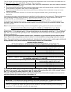
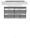
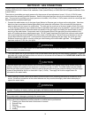
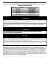
APPROXIMATE TIME/TEMPERATURE RELATIONSHIPS IN SCALDS
120°F (49°C) More than 5 minutes
125°F (52°C) 1½ to 2 minutes
130°F (54°C) About 30 seconds
135°F (57°C) About 10 seconds
140°F (60°C) Less than 5 seconds
145°F (63°C) Less than 3 seconds
150°F (66°C) About 1½ seconds
155°F (68°C) About 1 second
Keep clear of combination temperature and pressure relief valve discharge line outlet. The discharge may be
hot enough to cause scald injury. The water is under pressure and may splash.
For protection against excessive temperatures and pressure, install temperature and pressure protective equipment
required by local codes, but not less than a combination temperature and pressure relief valve certified by a
nationally recognized testing laboratory that maintains periodic inspection of production of listed equipment or
materials as meeting the requirements of the Standard for Relief Valves and Automatic Gas Shutoff Devices for Hot
Water Supply Systems, ANS Z21.22 and the Standard CAN1-4.4 Temperature, Pressure, Temperature and
Pressure Relief Valves and Vacuum Relief Valves. The combination temperature and pressure relief valve must be
marked with a maximum set pressure not to exceed the maximum working pressure of the water heater. The
combination temperature and pressure relief valve must also have an hourly rated temperature steam BTU
discharge capacity not less than the hourly rating of the water heater.
Install the combination temperature and pressure relief valve into the opening provided and marked for this purpose
on the water heater.
Note: Some models may already be equipped or supplied with a combination temperature and pressure relief valve.
Verify that the combination temperature and pressure relief valve complies with local codes. If the combination
temperature and pressure relief valve does not comply with local codes, replace it with one that does. Follow the
installation instructions above on this page.
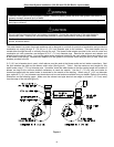
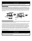
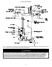
Install a discharge line so that water discharged from the combination temperature and pressure relief valve will exit
within six (6) inches (15.2 cm) above, or any distance below the structural floor and cannot contact any live electrical
part. The discharge line is to be installed to allow for complete drainage of both the combination temperature and
pressure relief valve and the discharge line. The discharge opening must not be subjected to blockage or freezing.
DO NOT thread, plug or cap the discharge line. It is recommended that a minimum clearance of four (4) inches
(10.2 cm) be provided on the side of the water heater for servicing and maintenance of the combination temperature
and pressure relief valve.
Do not place a valve between the combination temperature and pressure relief valve and the tank.
WARNING