


34
A qualified service technician should perform the following maintenance at the minimum periodic intervals suggested
below. In some installations, the maintenance interval may be more frequent depending on the amount of use and the
operating conditions of the water heater. Regular inspection and maintenance of the water heater will help to insure safe
and reliable operation.
1. Annual checks of the ignition systems, temperature controls and any other water heater controls are necessary to
ensure proper operation. Also, all safety shut-off valves must be checked to verify proper operation and tightness.
2. The entire combustion system must be sealed for this water heater to function properly. Make sure the burner access
panel is kept tightly sealed. The combustion air supply pipe at the rear of the water heater must be tightly sealed to
the dilution air tee and combustion air boot. Replace any damaged parts. The entire venting system and combustion
air supply parts must be inspected at least annually for integrity of all joints.
3. The flow of combustion and ventilation air MUST NOT be restricted. Keep the direct vent terminal openings clear of
objects, shrubs, snow, and debris. Check to make sure the vent terminal is not damaged.
4. At all times keep the water heater area clear and free from combustible materials, gasoline and other flammable
vapors and liquids.
5. Annually conduct a visual check of the pilot and burner flames to determine that they are burning properly. See
“Burner Flame Check” section for an illustration of the proper burner flame pattern.
6. At annual intervals check the flue baffles for deterioration and scale or carbon deposits. Clean if necessary and brush
the flue tubes if excessive scale or deposits are found on the baffles. Replace any baffles that have become
excessively warped or deteriorated. Check the flue collector gasket for integrity and replace if necessary. Cleaning
of the flue baffles and flue tubes should be done prior to cleaning the burners, since deposits may fall on the burners
during cleaning or checking the baffles.
7. Annually remove the main burner rack assembly to clean orifices and related parts of any dirt or other foreign
material. Inspect the burner ports for obstructions or debris and clean with a wire brush, vacuum, or use a mild
detergent solution to clean as needed. Inspect the pilot. Carefully clean the electrode and flame sense rod with
emery cloth. The spark electrode (rod closest to the pilot hood) gap should be 1/8” (3.2 mm). NOTE: It is imperative
for proper operation of the water heater that the main burner rack be replaced in the original location.
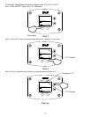
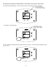
To remove the burner rack assembly, follow the procedure outlined below:
a) Shut off the gas and electrical supply to the water heater.
b) Remove the pilot tube fittings at the gas valve and combustion box.
c) Disconnect wires to gas valve. Open control box and disconnect pilot spark and flame sense wires.
d) Disconnect the gas pipe union below the gas valve.
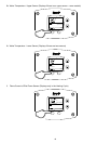
e) Remove the three screws securing the gasketed manifold pipe flange on the left side of the combustion box.
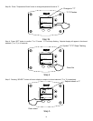
f) Remove the burner access panel screws and lower the hinged panel.
g) Carefully remove and push the pilot wire grommet into the combustion box with the pilot wires.
h) Disconnect the pilot tube fitting on the inside bulkhead fitting of the combustion box.
i) Unthread the gas pipe assembly from the manifold inside the combustion box.
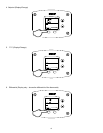
j) Remove the screw securing the curved burner shroud on the top center securing the burner assembly to the tank
skirt.
k) Slide out the burner rack assembly.
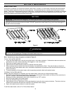
l) To remove the individual burners from the rack, the burner assembly shroud assembly must be removed from the
burner rack by removing the four (4) screws securing the shroud to the rack. The shroud must be reattached
to the burner rack after reinstalling the burners back in the rack.
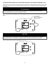
WARNING
Do not run out of propane gas. Damage to the water heater may occur.