


LTC 8600 | LTC 8800 Series en | 55
F.01U.127.393 | 2.0 | 2009.03 Instruction Manual Bosch Security Systems, Inc.
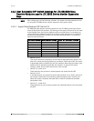
14.2.2 Middle Data Receiver DIP Switch S2
The lower DIP switch provides certain user-selectable options. These options are as
follows:
• Switch 1 of S2
This switch is reserved and should be left OFF.
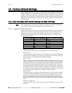
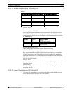
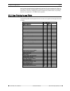
• Switch 2 and Switch 3 of S2
Up to eight (8) system keyboards can be connected to the rear panel of the
LTC 8802 Series Monitor Expansion Bay. DIP switches 2 and 3 determine the
system keyboard group that can be assigned. Follow the table below to select
the desired group.
• Switch 4 and Switch 5 of S2
These switches are reserved and should always be left OFF.
• Switch 6 of S2
When switch 6 is ON, the LTC 8816/00 data receiver module communicates
with system keyboards using the newer “6 poll byte” protocol. This format is
required to provide variable speed pan/tilt control capability for AutoDome
equipped camera sites. If it is necessary to communicate to older system key-
boards that are only compatible with fixed speed keyboard protocols, place the
switch in the OFF position.
• Switch 7 of S2
This switch determines the operational mode of the LTC 8816/00 and must
always be left ON.
• Switch 8 of S2
This switch determines the operational mode of the LTC 8816/00 and must
always be left OFF.
14.2.3 Lower Data Receiver DIP Switch S3
• The lower DIP switch does not currently provide any user-selectable options,
and all settings should be left in their OFF position.
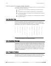
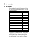
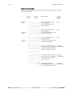
DIP Switch Number Factory Default Setting S2 DIP Switch Function
1OFF Reserved
2 OFF Keyboard Group
3 ON Keyboard Group
4OFF Reserved
5OFF Reserved
6 ON Keyboard Mode
7 ON Operational Mode
8 OFF Operational Mode
Switch 2 Switch 3 Keyboard Group
Off Off Reserved
Off On Keyboards 9-16 (Default)
On Off Keyboards 17-24
On On Keyboards 25-32