


LTC 8600 | LTC 8800 Series en | 109
F.01U.127.393 | 2.0 | 2009.03 Instruction Manual Bosch Security Systems, Inc.
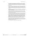
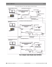
LTC 8569 Series Code Merger must be installed at the satellite site. The Code
Merger combines code generated by the main site and the satellite site, so both
sites have control over pan/tilt/zoom-equipped cameras located at the satellite site.
The LTC 8780 Series unit can then be connected to one of the data outputs of the
LTC 8569 Series unit.
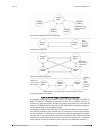
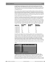
One or more monitor outputs from each satellite system are used as video trunk
lines to link the remote sites to the Main site. The number of trunk lines from a sat-
ellite site determines the maximum number of cameras from that site that may be
viewed simultaneously at the Main site. A satellite switcher model must be selected
so that it provides the desired number of local monitor outputs plus the number of
monitor outputs that will be used as trunk lines.
The Main site switcher must include sufficient camera inputs for local cameras plus
trunk lines. The maximum physical number of camera inputs or monitor outputs
used as trunk lines cannot exceed the capacity of the system. A single Main site
switcher can control multiple satellite sites up to its video input limit. If full matrix
switching is required at the Main site, the number of trunk lines from each satellite
site must equal the number of monitors connected to the Main site switcher. Multi-
ple independently controlled Main site systems can be combined to provide large
numbers of monitor outputs at the Main site. System capacities are listed below:
Since Main site Allegiant Series switchers support access to a large quantity of
remote satellite cameras, they provide additional logical camera numbers for identi-
fying the location of the satellite camera inputs in the system. These logical camera
numbers can also include titles which would appear on the Main site's monitors for
any remote cameras. Since each camera (anywhere in the system) must have a
unique camera number, logical camera numbers together with physical camera
inputs make up the total system camera capacity. Thus, there is a trade-off between
the total number of Main site cameras and the number of inputs used as trunk lines.
The more inputs used as trunk lines, the fewer there are for use as direct camera
inputs.
The Main site system must be programmed via the MCS LTC 8059/00 or the
LTC 8850/00 GUI to identify camera trunk line inputs as well as remote satellite
cameras. All systems must be configured with no duplicate camera numbers any-
where in the system. The installer should verify that the camera numbers pro-
grammed into the Start-up Camera field of the Monitor table are suitable for viewing
by respective operators. If there are Lockouts programmed into the system, specify-
System Type
Max. Camera
Inputs
Max. Monitor
Outputs
Max. No. of
Satellite Sites
LTC 8100 Series 8 2 8
LTC 8200 Series 16 5 16
LTC 8300 Series 32 6 32
LTC 8500 Series 64 8 64
LTC 8600 Series 128 16 128
LTC 8800 Series 256 64 256
LTC 8900 Series 4096 512 256
Model No. Maximum Number System Cameras*
LTC 8100 Series 264
LTC 8200 Series 272
LTC 8300 Series 288
LTC 8500 Series 320
LTC 8600 Series 1152
LTC 8800 Series 2304
LTC 8900 Series 6144
*Camera inputs at all sites, plus trunk lines.