


LTC 8600 | LTC 8800 Series en | 43
F.01U.127.393 | 2.0 | 2009.03 Instruction Manual Bosch Security Systems, Inc.
12 Main Power Connections
1. Attach the supplied AC power cord(s) between the bay(s) and appropriate AC
power source. Verify that power supply is configured for desired voltage input.
If necessary, instructions for changing the input voltage selection can be found
in the Maintenance section of this manual (See Chapter 19, “Maintenance Infor-
mation,” on page 83) Switch power ON to the bay(s). In multibay systems, the
bays can be powered up in any order.
NOTE The system may require several seconds to fully initialize after a power-up reset.
Up to one (1) minute may be required before a LTC 8802 Series Monitor Expan-
sion bay fully initializes. This time can vary based on the activity and general
size of the system.
2. Verify that the LEDs associated with the fuses are lit on all of the applicable
power supplies.
NOTE Upon power-up, the system monitors may momentarily display video output module
software version information.
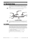
Installations having cameras powered from an AC phase different than that of
the Allegiant system may utilize the built in EXTERNAL SYNC input or vertical
PHASE ADJUST.
NOTE All cameras should be phased properly with each other before the EXTERNAL SYNC
or PHASE ADJUST feature is implemented.
The EXTERNAL SYNC input will accept composite video, composite sync, or out-
put from a Master Sync generator. Any one of the phased cameras may be used
as a master sync source to the system using the EXTERNAL SYNC input. To
implement this feature, simply connect the incoming video source (using a BNC
“T” connector) to both the appropriate camera BNC input and the EXTERNAL
SYNC input which is found on the rear of the Allegiant CPU bay. The front panel
illuminates the EXT SYNC LED. Alternatively, the PHASE ADJ on the front panel
of the power supply may be adjusted until the vertical interval switching is
achieved. The PHASE ADJUST has a range of about
130 degrees.
3. Reattach the front panel(s) to the bay(s).
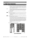
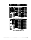
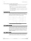
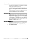
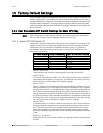
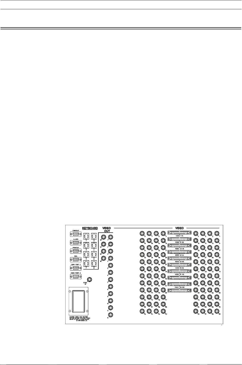
Figure 14: LTC 8600 Series Rear Panel