


30 | en LTC 8600 | LTC 8800 Series
Bosch Security Systems, Inc. Instruction Manual F.01U.127.393 | 2.0 | 2009.03
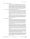
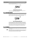
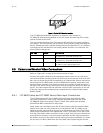
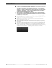
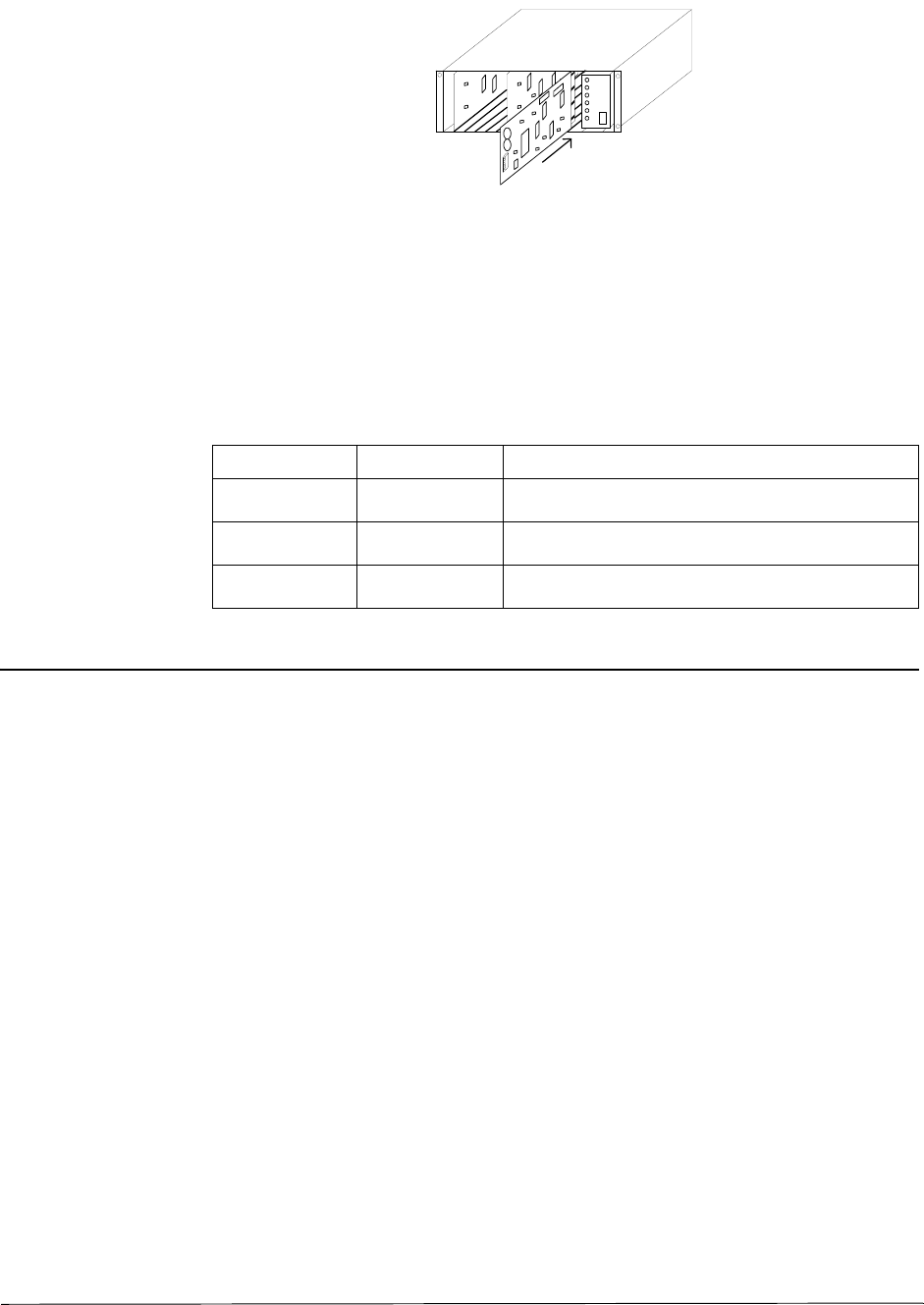
Figure 7: Typical CPU Module Insertion
If an LTC 8802 Series Monitor Expansion is supplied, it will contain an
LTC 8816/01 Data Receiving Module in this slot. Install the main bay CPU or data
receiver module at this time.
The circuit board contains three (3) 8-position DIP switches for system configura-
tion options. The DIP switches can be used to modify certain system operating con-
ditions. Review the Factory Default Settings Section to determine if it is necessary
to change the DIP switches from the factory default positions. For reference, the
factory default settings are:
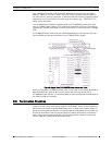
8.5 Camera and Monitor Video Connections
Refer to “Figure 14:” on page 43 for the next series of steps.
Connect the system cameras to the appropriate video inputs, but as a minimum
connect one known operating camera to video input #1 on the rear of the main CPU
bay. Use only those inputs that correspond to an installed VIM. Special instructions
concerning the LTC 8600 Series or the LTC 8800 Series systems, termination, and
expansion bays are given in the sections below. Also connect desired monitors to
the rear of the main CPU bay, ensuring to connect at least one monitor to video out-
put #1. The video outputs are the left-most column of BNC connectors on the rear
of the bay. Use only those outputs that correspond to an installed Video Output
Module (VOM).
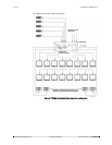
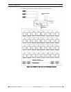
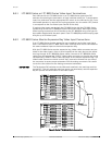
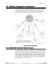
8.5.1 LTC 8600 Series and LTC 8800 Series Video Input Connections
The LTC 8601 Series and the LTC 8801 Series main bays have 96 direct BNC
connectors available for video input. Cameras above 96 require the use of the
LTC 8808/00 Video Interconnect (“Patch”) Panel. Each patch panel provides
32 additional BNC connectors for video input.
Patch panels are connected to the rear of the main bay using the supplied ribbon
cables. Each cable can carry video for up to 16 cameras. Two (2) cables can be
attached to each patch panel to support up to 32 cameras per panel. Each ribbon
cable should be attached to the appropriate “VIDEO” connector on the rear of the
main bay. The ribbon cable connectors contain a small “key” protrusion formed into
one side of the connector to assure proper placement into the mating connectors.
Be careful not to force the cables into the mating connectors backwards. For exam-
ple, the two (2) ribbon cables from the first patch panel (supporting the 32 cam-
Bay Type Module DIP Setting
LTC 8601 Series LTC 8610/01 CPU S1 and S3, All OFF
S2, Switch 5, 7, and 8 ON; All others OFF
LTC 8801 Series LTC 8810/01 CPU S1 and S3, All OFF
S2, Switch 5, 7, and 8 ON; All others OFF
LTC 8802 Series LTC 8816/01 S1 and S3, All OFF
S2, Switch 3 and 7 ON; All others OFF