


54 | en LTC 8600 | LTC 8800 Series
Bosch Security Systems, Inc. Instruction Manual F.01U.127.393 | 2.0 | 2009.03
14.2 User Selectable DIP Switch Settings for LTC 8816/00 Data
Receiver Modules used in LTC 8802 Series Monitor Expansion
Bays
NOTE After changing any of the following switches, the system must be powered off and
on using the LTC 8802 Series monitor expansion main power switch.
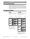
14.2.1 Upper Data Receiver DIP Switch S1
LTC 8816/00 data receiver modules supplied in the LTC 8802 Series bays contain
three (3) 8-position DIP switches. The settings of the upper DIP switch do not need
to be changed from their factory default positions except when it is necessary to
change the factory default format for the internal raster generator or if a problem
occurs downloading new firmware into the data receiver module. The following
table list these functions:
• Switch 1 of S1
This switch selects the frequency of the internal raster generator used for dis-
play of on-screen text during video loss conditions. When set to OFF, the raster
is generated at 60 Hz (default for 120 VAC models). When ON, the raster is gen-
erated at 50 Hz (default for 220-240 VAC models). To set the DIP switch
changes. power the unit OFF and then turn the unit ON.
• Switch 2, 3, and 4 of S1
These switches are not used in these systems and should be left OFF.
• Switch 5 of S1
In the ON position, this switch forces the data receiver into a “boot” mode so it
can accept a download of an operating system program via its console port.
When this mode is enabled, the baud rate is fixed to 115200 and hardware
handshake is ON.
• Switch 6, 7, and 8 of S1
These switches do not currently provide user selectable options and should be
left OFF.
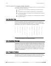
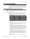
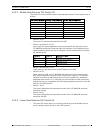
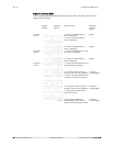
DIP Switch Number Factory Default Setting “Upper” S1 DIP Switch Function
1 ON/OFF Raster Generator Mode
2OFF Not Used
3OFF Not Used
4OFF Not Used
5OFF Boot Mode
6OFF Not Used
7OFF Not Used
8OFF Not Used