


LTC 8600 | LTC 8800 Series en | 29
F.01U.127.393 | 2.0 | 2009.03 Instruction Manual Bosch Security Systems, Inc.
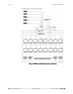
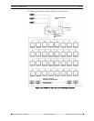
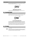
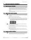
being used, the modules should be inserted in a left-to-right manner so that the
lower camera numbers are used first.
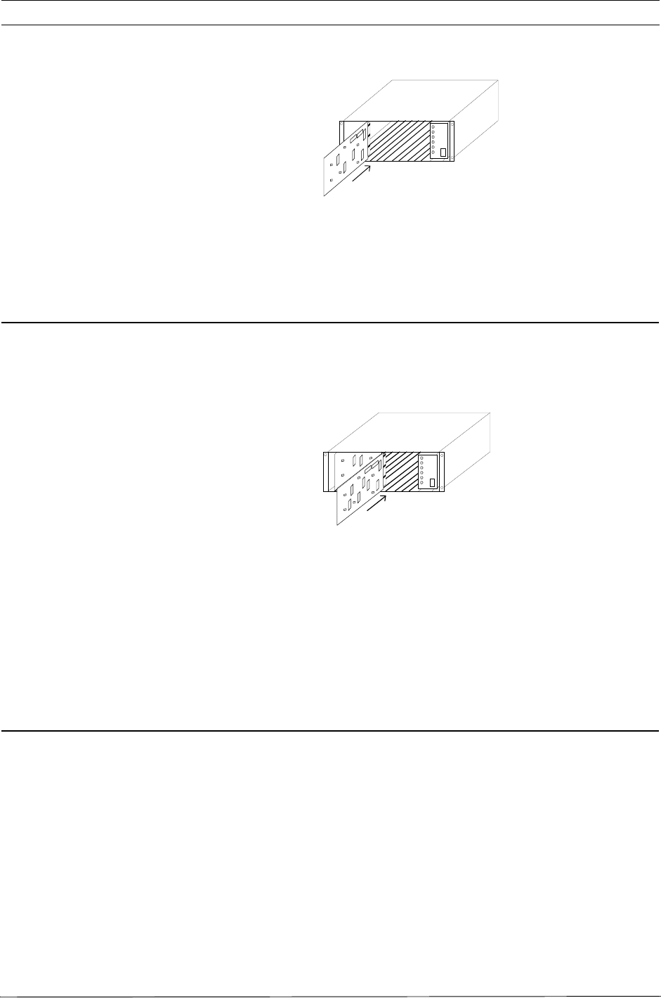
Figure 5: Typical Video Input Module Insertion
The VIMs are identical and are interchangeable within the designated VIM slots
without having to make any changes to the module.
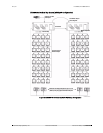
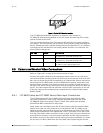
8.3 Video Output Modules
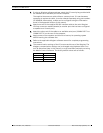
Counting from left to right beginning with slot 9, install the appropriate number of
Video Output Modules (VOM) into these slots. If fewer than the maximum number
of VOMs are installed, there will be empty slots between the Input and the Output
Modules, so make sure that the VOMs are inserted into the correct slots.
Figure 6: Typical Video Output Module Insertion
If the LTC 8802 Series Monitor Expansion Bay is being used, it should be loaded
with VIMs in the same fashion. The Main CPU Bay should be FULLY loaded with 8
output modules before putting output modules into the Monitor Expansion Bay.
Remaining output modules are inserted into the Monitor Expansion Bay starting at
slot 9. If fewer than the maximum number of outputs are being used, the Monitor
Expansion Bay may contain fewer Output Modules than the Main CPU Bay.
All VIMs are identical and are interchangeable within the designated VOM slots.
8.4 CPU Module
The slot to the left of the power supply in the main CPU bay is reserved for the sys-
tem CPU module.
NOTE The CPU module contains two (2) lithium batteries mounted on the component side
of the printed circuit board. A red rectangular insulating tag may be installed in
between the top of the batteries and the battery holder clip. This tag prevents bat-
tery drainage during stocking. Remove tag if so equipped.