


28 | en LTC 8600 | LTC 8800 Series
Bosch Security Systems, Inc. Instruction Manual F.01U.127.393 | 2.0 | 2009.03
8 Installation Procedure
8.1 Main CPU Bay Installation
Before discarding the shipping cartons, verify that the various pieces of equipment
have no evidence of carrier damage.
CAUTION Do not apply power to the equipment until instructed to do so.
1. Remove the front panel of the main CPU bay and the front panels of any sup-
plied expansion bay (LTC 8802 Series) by loosening the four (4) corner fasten-
ers.
2. Install the power supply in far right position of the main CPU bay insuring
proper alignment and seating of the module into the rear mating connector. Ver-
ify that the power supply ON/OFF switch is in the OFF position. Repeat this
procedure for any supplied LTC 8802 Series Monitor Expansion bay.
3. Install the four screws and star washers (supplied) on the rear panel of the
bay(s) surrounding the power supply line cord to fasten the power supply
securely in place.
CAUTION If the allegiant card cage is to be transported, the main power supply should be
removed to prevent possible damage to the bay's internal parts.
4. If the bay(s) are to be installed into a standard 19-inch EIA rack, remove the
four (4) rubber bumper foot pads found on the bottom of the bay before install-
ing the unit in the rack. Four (4) holes are provided for mounting the bay(s) in
the rack. If any LTC 8802 Series Monitor Expansion bay is supplied, it should be
located as close as possible to the LTC 8801 Series Main CPU bay to facilitate
cable interconnections.
5. Install the LTC 8600 Series, the LTC 8800 Series, and the LTC 8802 Series Moni-
tor Expansion bays so that there is at least 9 cm (3.5 in.) of clearance above
and below the bay. This clearance is necessary to allow for proper cooling of
the system. Failure to provide proper clearance may cause the equipment to
exceed its recommended operating temperature range.
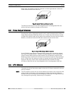
NOTE An LTC 8802 Series Monitor Expansion bay should be located close enough to the
TC8801 so that you can connect the units with the supplied 2 m (6 ft) data intercon-
nect cable
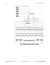
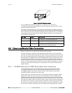
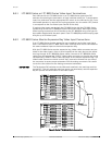
8.2 Video Input Modules
Termination switches on the Video Input Modules (VIM) must be set to the correct
position prior to installation. If necessary, see Section 8.6 “Termination Practices,”
on page 31 prior to actually installing the VIM on these systems.
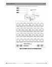
The appropriate number of VIMs should be installed in the main bay starting with
the left most slot. If the LTC 8802 Series Monitor Expansion Bay is being used, it
should receive the same number of VIMs as the main bay. If less than full capacity is