


116 | en LTC 8600 | LTC 8800 Series
Bosch Security Systems, Inc. Instruction Manual F.01U.127.393 | 2.0 | 2009.03
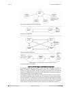
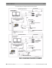
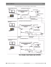
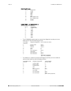
C.4 Signal Distribution Unit
CONNECTION TO MAIN BAY
The Distribution unit is supplied with a 3 m long (10 ft) multiconductor cable with
9-pin D-type connectors. Power to the unit is provided by the Allegiant's main bay
using the supplied cable. The cable should not be extended so it is recommended
that the unit be located close to the main bay.
DISTRIBUTION OUTPUTS
Only shielded twisted pair wire should be used between the Distribution unit and
the camera site receiver/drivers. Connection to the Distribution unit is made to
removable screw terminal type blocks. Each output is rated to handle up to eight
receiver/driver loads as in a daisy chain configuration to a maximum of 1.5 km
(5000 ft) using a 18 gauge wire (Belden 8760 or equivalent).
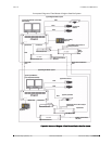
C.5 Receiver/Drivers
CODE INPUT
The code input is supplied by the shielded twisted pair cable from the Signal Distri-
bution unit. This is connected to a removable screw terminal type block which has
provisions for “looping” the code cable to another receiver/driver.
OUTPUT CONNECTIONS
All pan/tilt and lens connections will require multiconductor cable. Refer to the
appropriate specification sheet for cable gage, number of conductors required, and
maximum distances allowable. The lens cables and any pre-position cables should
be kept shielded from other signal wires to minimize interference.