


7
CG15, CG25, CG50 Burner Manual
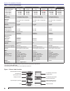
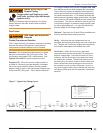
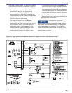
Electrical Supply
Check the nameplate on the burner to verify that the
power connections available are correct for the burner.
Refer to Figure 1. All power must be supplied through
fused disconnect switches and comply with the latest
edition of National Electric Code NFPA 70 (Canada CSA
C22.1) and all other local or applicable codes.
Verify Burner Components
Burner model can be checked from burner carton or
rating label on burner.
Flange mounting arrangement (Includes high-
temperature gasket and/or fi ber rope for pressure fi ring).
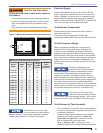
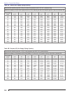
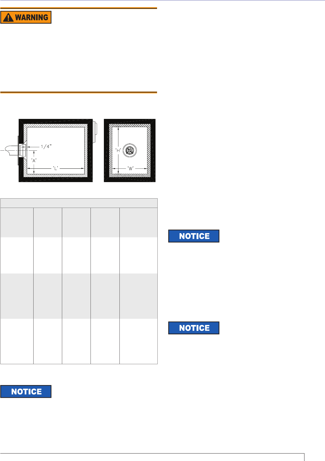
Verify Firing Input Range
Refer to appliance manufacturer’s instructions (if
available) for the fi ring input range. Otherwise the
maximum recommended fi ring range for the burner
depends on the length and width of the fi ring chamber
and the distance from the burner center to the chamber
fl oor. Verify that the chamber dimensions are at least as
large as the minimum values given in Figure 2. If the
appliance dimensions are smaller, reduce the fi ring rate
accordingly.
Minimum Inside Dimensions (inches)
Burner
Model
Width
‘W’
Height
‘H’
Length
‘L’ at Min
H & W*
Burner
Head
Centerline
to fl oor ‘A’
CG15.1S 15 16 42 7
CG15.2S 16 17 45 8
CG15.3S 17 18 47 8
CG15.4S 18 19 50 9
CG25.1S 19 20 45 9
CG25.2S 20 21 48 10
CG25.3S 21 22 50 10
CG25.4S 22 23 52 11
CG25.5S 23 25 55 11
CG50.1S 21 23 55 10
CG50.2S 22 24 58 11
CG50.3S 24 26 62 12
CG50.4S 25 27 65 12
CG50.5S 27 29 70 13
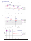
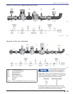
Verify Burner Air Tube Assembly
The information in this section may be disregarded if
the burner supplied by the appliance manufacturer is
a matched component.
Maximum fi ring capacity depends on the furnace
pressure. Use the charts shown in Figure 3A,
Figure 3B, and Figure 3C, to verify the correct
burner confi guration for the input rate.
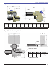
Refer to Figures 4 & 5 to verify the air tube
assembly length and mounting insertion dimensions.
○
○
○
Figure 2 - Minimum Combustion Chamber Dimensions
Test For Gas Pipe Leaks
Leaking gas could result in asphyxiation, explosion,
or fi re hazard.
The gas supply piping must be absolutely leak-free.
Pressure test the gas piping with air that is at least
three times greater than the gas pressure being
used.
Verify that there are no leaks before proceeding.
y
y
y
Dimensions shown are for cast
iron sectional boilers with uptakes
between sections. For minimum dimensions of other
furnace types consult R. W. Beckett Corporation.
Flames are shaped by their
furnaces and by its fl ue locations.
Increased height and width can decrease the length
requirement. When shaping is too severe fl ames
impinge on the walls. Impingement causes CO and
carbon deposits and may damage the wall. Maintaining
these minimum dimensions should prevent impingement,
but smaller furnaces may be acceptable depending
upon the results of applications testing. We recommend
factory testing of all new burner/furnace combinations by
the furnace manufacturer and/or R. W. Beckett Corp.
The volume of the furnace also
infl uences the combustion process.
R. W. Beckett Corp. recommends at least 1 cubic foot of
furnace volume for each 150,000 BTU/Hr of fi ring rate.
Section: Pre-installation Checklist