


23
CG15, CG25, CG50 Burner Manual
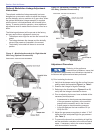
Verify Input Firing Rate
Clock the meter, correct for pressure and
termperature to get SCFH and calculate the
input fi ring rate. Compare the calculated rate to
the specifi ed input for the boiler found on the
specifi cation sheets and on the rating plates for
the burner and boiler. Do not exceed the specifi ed
maximum input for the boiler.
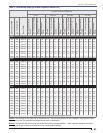
Attach a manometer to the manifold test port, clock
the meter, and adjust the regulated pressure until the
specifi ed input level is achieved. Refer to Table 3.
Be sure to set the breech or furnace pressure to the
correct value, since this will have an effect on the
manifold pressure.
1.
2.
3.
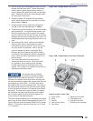
B) At burner start-up - Note, as soon as the burner
lights, be prepared to adjust the butterfl y valve to set the
low fi re rate adjustment.
Monitor the fl ame through the observation port. If
it appears to be too rich (yellow-orange fl ame),
move the butterfl y valve shaft slot setting toward a
more vertical position. (This adjustment is made
by turning the nut holding the spring-loaded swivel
on the butterfl y valve arm. If insuffi cient adjustment
is available by this method the butterfl y valve shaft
can be repositioned in the arm. Care must be taken
to make only small changes.)
Use a fl ue gas analyzer to check the fl ue gas
ratings for O
2
and CO. Your target should be 4% O
2
and CO should be well below 50 PPM. (Note that
the CO is usually near 0 at 4% O
2
.)
If the O
2
and CO levels are not on target, turn the
low fi re adjustment nut as required to meet the
target listed in Step 2.
Check the low fi re rate. Either clock the meter or
compare the manifold pressure drop to factory
standards. Adjust the low fi re cam setting in the
damper motor (if necessary refer to the Initial
Air Setting procedure described previously) and
the butterfl y valve shaft slot position as described
in Step 1. Refer to Step 2 in this procedure and
double check the O
2
and CO readings.
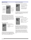
When low fi re is set, use the modulation controller
to manually step the burner up to its high fi re rate.
Check fl ue gas O
2
and CO. Your target should be
3% O
2
. CO should be well below 50 PPM, and is
usually near 0 for that O
2
. Adjust the regulated gas
pressure as required to meet the target.
Check the high fi re rate and adjust the high fi re cam
setting and regulated gas pressure as required to
meet the target. (If necessary, refer to the Initial Air
Setting procedure described previously.)
Using the modulation controller, manually step
the burner back down to low fi re and verify the O
2
and CO ratings. If the high fi re adjustments were
signifi cant they may have affected the low fi re
settings as well. Refer to Step 4 in this procedure
to make adjustments as necessary.
Using the modulation controller, manually step the
burner through its range, stopping at several points
to check O
2
and CO measurements.
After you are satisfi ed with the modulation linkage
adjustments secure all linkage fasteners and
continue the start-up procedure.
1.
2.
3.
4.
5.
6.
7.
8.
9.
10.
It is acceptable for a burner with
linkage control of the fuel to show
2% variation in O
2
through the range as long as O
2
stays
above the target points. If the O
2
drops below the target
points it may lead to a CO problem. Moving the damper
arm position on the damper shaft changes mid-range
O
2
. Loosening the clamping screws and moving the
swivel end of the arm downward increases midrange O
2
,
upward decreases it. This change will affect the low fi re
O
2
setting, and you’ll need to re-set it.
Section: Start the Burner