


30
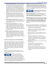
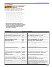
Burner Head Adjustment - There is an optimum gas orifi ce size and burner head setting for each fi ring rate of
the burner. The gas orifi ce size sets the gas fl ow velocity; the head setting establishes the airfl ow velocity.
When those velocities are properly matched the burner provides its best performance and stability.
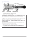
The gas orifi ce size is built into the burner head. You can verify the correct selection by looking for the burner
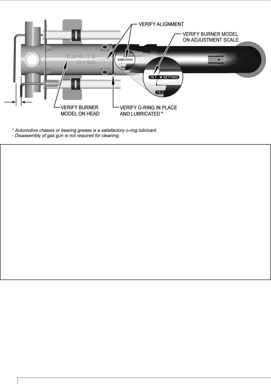
model number stamped on the top centerline of the stainless steel tube that forms the base of the burner head.
It should match the model number on the Beckett burner data label on the blower housing.
The head setting is established by a notched sleeve on the gas tube that can be rotated to positions on a scale
marked by the burner’s model number. The scale should normally be set to the model number on the Beckett
burner data label. (If specifi c application requirements dictate an alternate head setting it will be noted by a
label on the gun assembly.)
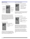
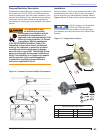
For normal service requirements it is not necessary to disassemble the head from the gas tube. If you
disassemble the gas gun, make sure that when you re-assemble it:
The adjustment scale is set to the correct position as indicated by the burner model number or Gun Label.
The alignment marks on the head, scale and stop are in alignment.
The O-ring between the head and the adjustment scale is in place, is lubricated with grease, and is
compressed between the head and scale as the setscrews that retain the head are tightened.
1.
2.
3.
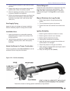
Figure 15B – Gas Gun Assembly
3/8”
Section: Maintenance and Service