


15
CG15, CG25, CG50 Burner Manual
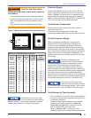
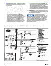
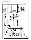
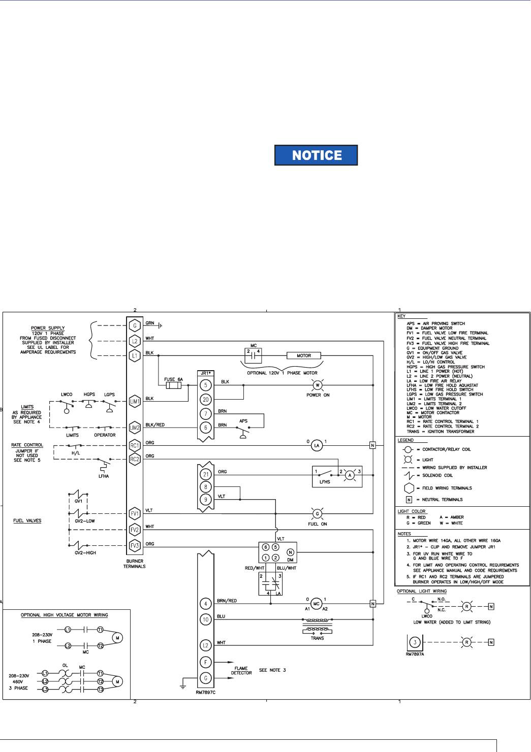
Figure 9A - Typical Wiring Using Model RM7897C for High/Low Control (For Reference Only)
continuing to detect a fl ame, the burner will operate
in the RUN mode until the load demand is satisfi ed
or a limit opens.
For High/Low control wiring (Figure 9A), if
terminals RC1 and RC2 are jumpered, the
burner operates in the Low-High-Off mode. The
burner starts at Low and goes to High after the
fl ame stabilization period. Flame is extinguished
when the load is satisfi ed or a limit opens, and
the burner is sent to post purge.
For High/Low control wiring (Figure 9A), if
a high / low control has been wired between
terminals RC1 and RC2 the burner starts at Low
and is released to go to High after the fl ame
stabilization period. It can repeatedly cycle
between low and high as necessary to meet
load demand until the load is satisfi ed or a limit
opens, and the burner is sent to post purge.
○
○
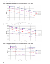
For modulating control wiring (Figure 9B), the
burner starts at Low and is released to modulate
after the fl ame stabilization period. It can
modulate between low and high as necessary to
meet load demand until the load is satisfi ed or a
limit opens, and the burner is sent to post purge.
Load Satisfi ed – The fuel valves are closed. After
a 15 second post purge, the burner switches to idle
until the next call for operation.
○
8.
This operation sequence is
typical and for reference only. The
primary control could vary, depending on the customer
specifi cation and code requirements. For the specifi c
operating sequence that applies to your installation,
consult the appliance manufacturer’s directions, wiring
instructions, and control manufacturer’s literature
supplied with your burner.
Section: Sequence of Operation