


18
Start the Burner
Initial Air Settings
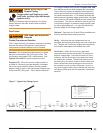
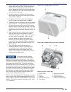
If your burner was built for a specifi c OEM (Original
Equipment Manufacturer) application, the “Mfr’s
Settings” label (see Figure 1) will indicate the application
and the initial air settings made at Beckett. Please verify
those settings using the following procedure.
If your burner was not built for a specifi ed application,
the following steps outline the procedure for initially
setting the damper (these settings may be different from
settings specifi c to a particular OEM).
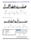
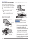
Refer to Figure 10A and 10B for this procedure.
Remove the cover screw (A) then the cover (B) and
set aside.
1.
plates, enclosures and guards are in place and
securely fastened.
When available, refer to the appliance
manufacturer’s instructions and install the burner
accordingly.
6. Test Instruments
The following calibrated test equipment is required
to properly install the appliance. Whether these are
included in one kit or are individual test components,
they should be calibrated and in good working order.
A combustion analyzer capable of measuring
oxygen (or carbon dioxide), carbon monoxide, stack
temperature, ambient temperature, and appliance
effi ciency.
Electrical multi-meter capable of measuring voltage,
ohms, amps, and DC micro-ammeter for measuring
the fl ame signal. These could be included in one
meter or separate meters, but should be calibrated
and accurate.
Calibrated manometers and gauges capable of
measuring all pressure ranges in the gas supply and
appliance draft. This could typically range from a
few psi to 0.01” W. C.
Having several manometers or U tubes with the
correct range can simplify the testing and set up
procedures.
○
○
○
○
○
○
Burner Start Procedure
(Before proceeding, turn off and lock out electrical
power and close the main leak test cock to shut off
gas to the burner.)
With the power and main gas supply to the burner
turned off, make sure gas has not accumulated in
the boiler or fl ues.
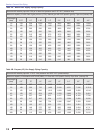
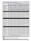
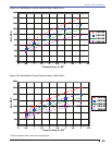
Check the initial air settings for the input fi ring rate.
Check the manufacturer’s settings either on the
nameplate shown in Figure 1 or listed in Table 3.
If adjustment is necessary refer to Figures 10A
& 10B and set the damper motor cam so that
the indicator points to the values shown on the
nameplate or listed in Table 3.
With the main gas supply valve closed. Set the
limit or controller to call for heat then apply power
to start the burner. Reset the high and low gas
pressure switches if necessary.
In order to check the function of each component
(i.e: fl ame safeguard sequence, airfl ow proving
switch, ignition transformer, gas valves, safety
lockout timing, etc.), with the gas supply closed off,
monitor a complete burner run sequence. Note that
the fl ame safeguard control will lock out since the
fuel supply has been closed off.
If component operation sequence and function is
correct, reset the fl ame safeguard and initiate a
new cycle. Monitor the start-up cycle and manually
open the main leak test cock as soon as the fl ame
safeguard powers the safety shutoff valves. If the
boiler room is quiet you may be able to hear the valve
open, if not you can generally place your hand on the
valve and feel it open. After you have observed main
fl ame for a brief time, trip any of the switches in the
limit string to shut the burner down. Monitor the fl ame
and safety shutoff valves to assure that shutdown
is controlled by the valves and that they operate
properly. With this test passed you may safely initiate
automatic start-ups on subsequent cycles.
1.
2.
3.
4.
5.
Professional Installation
and Service Required
Incorrect installation and mishandling of start-
up could lead to equipment malfunction and
result in asphyxiation, explosion or fi re.
This burner must be installed and prepared for start-
up by a qualifi ed service technician who is trained
and experienced in commercial gas burner system
installation and operation.
Do not attempt to start the burner unless you are
fully qualifi ed.
Do not continue with this procedure until all items in
the ‘Prepare the Burner for Start-up’ section have
been verifi ed.
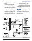
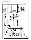
Carefully follow the wiring diagrams, control
instruction sheets, fl ame safeguard sequence
of operation, test procedures and all appliance
manufacturer’s directions that pertain to this
installation.
If any of these items are not clear or are unavailable,
call Beckett at 1-800-645-2876 for assistance.
y
y
y
y
y
Section: Start the Burner