


32
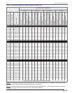
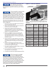
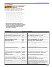
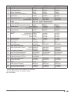
Table 4 - Propane Restrictors Replacement Part
Numbers
Burner Model
Restrictor
Part Number
Restrictor
Inside
Diameter
O-Ring Part
Number
CG15.1S 3246709U 0.532 3226401U
CG15.2S 3246710U 0.576 3226401U
CG15.3S 3246711U 0.623 3226401U
CG15.4S 3246712U 0.677 3226401U
CG25.1S 3246713U 0.712 3226402U
CG25.2S 3246714U 0.742 3226402U
CG25.3S 3246715U 0.796 3226402U
CG25.4S 3246716U 0.833 3226402U
CG25.5S 3246717U 0.889 3226402U
CG50.1S 3246718U 0.925 3226403U
CG50.2S 3246719U 0.980 3226403U
CG50.3S 3246720U 1.031 3226403U
CG50.4S 3246721U 1.103 3226403U
CG50.5S 3246722U 1.150 3226403U
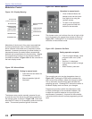
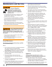
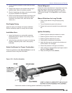
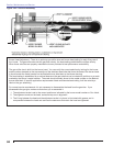
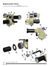
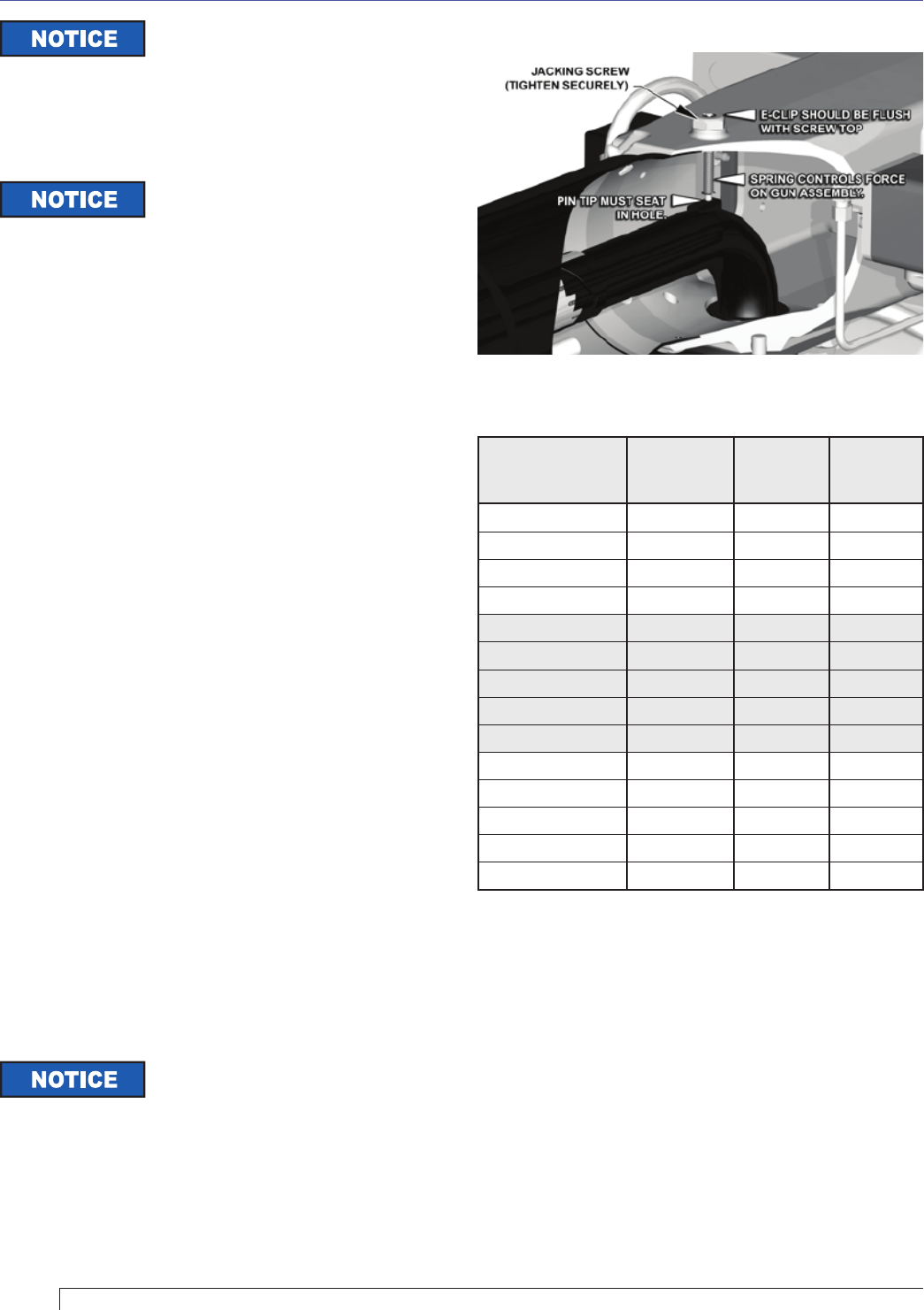
Figure 18 – Gas Gun Installation
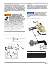
Remove the jacking screw (B) from the housing to
free the internal gas tube (C).
Gently rock the internal gas tube (C) to loosen the
tube from the burner housing (D).
Inspect the O-rings and insure that they are
properly lubricated. (A silicon O-ring lubricant is
recommended, but automotive chassis or bearing
grease is an acceptable substitute.)
Referring to Figure 17, place the restrictor (F)
with pre-attached, pre-lubricated O-ring (G) into
the internal gas tube (C). Use your hand to press
the restrictor into the tube. The O-ring will hold the
restrictor in place.
Insure that the O-ring (H), attached to the outside
diameter of internal gas tube, is properly lubricated
and seated against the fl ange on the internal gas
tube.
Install the internal gas tube (C) back into the
housing, refer to Figure 16. Fit the end of the tube
into the external gas manifold (E).
Re-install the jacking screw (B). (Refer to the above
notice for installation details.)
Fill out and place the supplied Conversion Data
Plate adjacent to the rating plate.
Complete and attach the supplied Adjustment Data
1.
2.
3.
4.
5.
6.
7.
8.
9.
Use authorized replacement parts
only. Restrictors are precision-
machined parts and O-rings are rated for fuel contact.
Do not attempt to replicate or modify any parts. Refer to
Table 4.
The gun assembly is secured inside
the air tube by a spring-loaded
jacking screw. It is spring loaded in order to control the
force it can impose on the gun assembly. When installing
the jacking screw look inside the air tube to verify that
the pointed tip of the jacking screw pin is seated into the
small slot on the locating pad on top of the gun. There is
also an external verifi cation of correct assembly: when
the screw is fully tightened, the e-clip on the top of the
center pin should come fl ush with the top of the screw.
Refer to Figure 18.
With the gas restrictor installed,
as shown in Figures 16 & 17,
all burner air adjustments and gas manifold pressure
adjustments for propane will be approximately the same
as the natural gas adjustments shown in the burner
manual, or printed on the “Mfr’s Settings” label on the
burner housing. For a copy of the current burner manual
go to http://www.beckettcorp.com/protect/tech.asp. If
furtherTechnical assistance is required, call 800-645-
2876, Monday thru Friday, 8AM to 5PM EST.
Section: Maintenance and Service