


19
CG15, CG25, CG50 Burner Manual
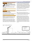
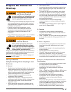
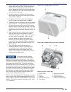
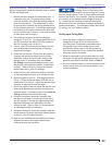
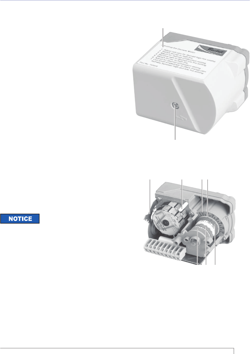
Figure 10A - Damper Motor with Cover
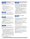
Figure 10B - Damper Motor with Cover Removed
Push in on pin (G) to disengage the motor from the
damper shaft and cam stack. Rotate the damper
shaft by hand to place the adjustment cams in a
position where their adjustment scale can be easily
seen. Release pin (G) to secure the damper shaft
and cam stack to the motor.
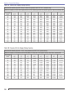
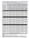
Using the wrench (C) supplied with the damper
motor, adjust the blue low fi re cam (D) to the initial
setting listed in Table 3.
Using the same wrench, adjust the red high fi re
cam (H) to the initial settings listed in Table 3.
To adjust the high fi re transition, use a small straight
edge screwdriver. For high/low fi ring burners, turn
the white adjustment screw located in the orange
transition cam (J) until the cam indicator is half way
between the high and low settings on the scale. For
modulating burners the orange transition cam is not
used.
After setting all the cams, make sure the damper
shaft and cam stack is set between its low fi re
setting and its high fi re setting. (If you don’t it may
not move when it is powered.) Push in pin (G),
move the damper by hand so that notch (E) is
between the low fi re setting and high fi re setting
on scale (F), then release pin (G) to re-engage the
motor. When the motor is powered it will go to its
low fi re setting.
This initial setting should be adequate for
starting the burner at low fi re. Once the burner
is in operation, the air setting will be adjusted
for best performance as discussed later in this
manual. Don’t forget to re-install the cover after all
adjustments have been made.
2.
3.
4.
5.
6.
7.
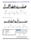
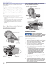
The damper plate is attached
by screws to its shaft, and bears
against a fl at on the shaft for alignment. The shaft is
secured to the damper motor by a sleeve coupling with
two setscrews bearing against the damper shaft and two
more against the motor shaft. The motor shaft has a
fl at matching the one on the damper shaft. The fl ats on
the damper shaft and the motor shaft should be aligned
so that the position indicator in the damper motor reads
accurately. The best way to align the fl ats is to tighten
the setscrews that bear against the fl ats on the shafts
fi rst, and then tighten the ones that bear against the
round surface of the shafts afterward.
The test for proper alignment is to disengage the damper
motor from its shaft using the disengaging pin (Item G in
Figure 10B) and rotate the damper plate to its full closed
position. The position indicator should point to 0° within
+/- 5° tolerance.
A - Cover screw
B - Cover
C - Wrench
D - Low fi re cam (blue)
E - Cam notch
F - Damper motor scale
G - Disengaging pin
H - High fi re cam (red)
J - Transition cam (orange)
Legend (Figures 10A & 10B)
A
B
HDJ
EFGC
Section: Start the Burner