


21
CG15, CG25, CG50 Burner Manual
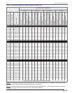
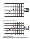
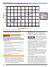
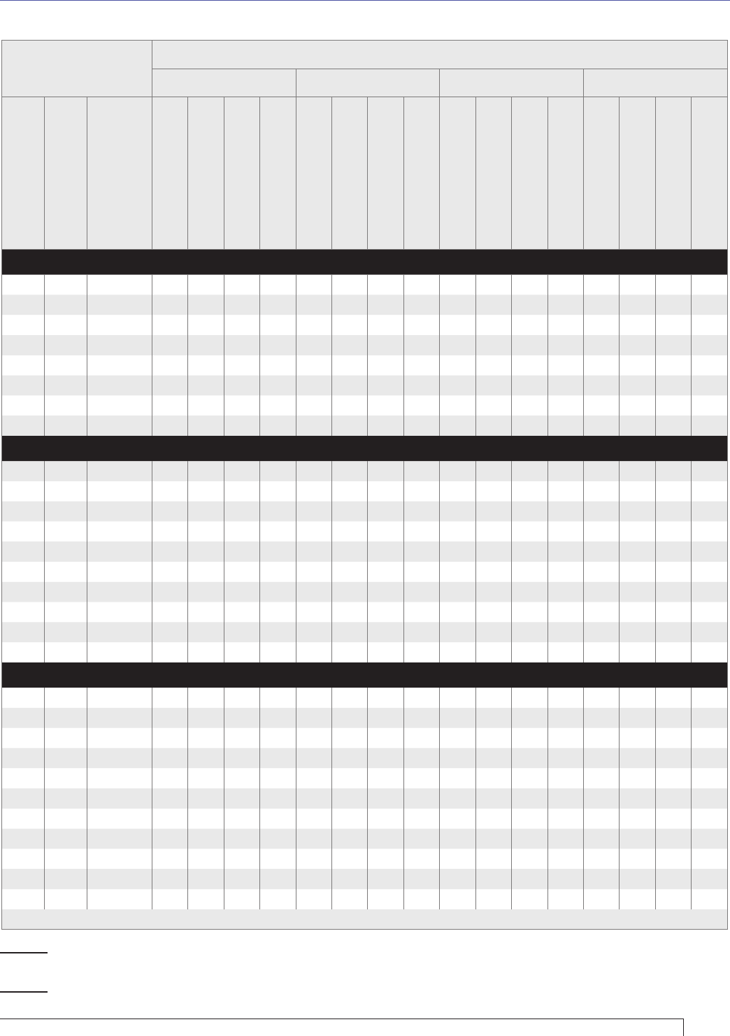
Table 3 - Initial Burner Settings for Both Propane & Natural Gas
Furnace Pressure at High Fire
0” W.C. 0.25” W.C. 0.50” W.C. 1.00” W.C.
High Fire Rate MBH
Low Fire Rate MBH
Burner Model
Low Fire Gas Pressure,
inch WC
Low Fire Damper Setting
High Fire Gas Pressure,
inch WC
High Fire Damper
Setting
Low Fire Gas Pressure,
inch WC
Low Fire Damper Setting
High Fire Gas Pressure,
inch WC
High Fire Damper
Setting
Low Fire Gas Pressure,
inch WC
Low Fire Damper Setting
High Fire Gas Pressure,
inch WC
High Fire Damper
Setting
Low Fire Gas Pressure,
inch WC
Low Fire Damper Setting
High Fire Gas Pressure,
inch WC
High Fire Damper
Setting
CG15
800 468 CG15.1S 0.9 9 2.7 25 1.0 9 2.9 26 1.1 9 3.2 27 1.3 10 3.7 31
900 468 CG15.1S 0.9 9 3.4 32 1.0 9 3.7 34 1.1 9 3.9 37 1.2 10 4.4 43
950 548 CG15.2S 0.9 12 2.6 30 0.9 13 2.9 33 1.0 13 3.1 36 1.2 14 3.6 42
1050 548 CG15.2S 0.9 12 3.2 38 0.9 13 3.4 48 1.0 13 3.7 58 1.1 14 4.2 84
1150 641 CG15.3S 0.9 16 2.8 42 0.9 17 3.1 49 1.0 17 3.3 56 1.2 19 3.8 74
1250 641 CG15.3S 0.9 16 3.3 52 0.9 17 3.6 68 1.0 17 3.8 85 - - - -
1300 750 CG15.4S 0.9 20 2.7 51 1.0 21 2.9 66 1.0 22 3.2 80 - - - -
1400 750 CG15.4S 0.9 20 3.1 66 1.0 21 3.3 100 - - - - - - - -
CG25
1350 669 CG25.1S 0.7 17 2.7 38 0.7 17 3.0 38 0.8 17 3.2 39 0.9 18 3.7 41
1450 669 CG25.1S 0.7 17 3.1 41 0.7 17 3.4 41 0.8 17 3.6 42 0.9 18 4.1 41
1550 774 CG25.2S 0.7 20 2.7 41 0.7 20 2.9 42 0.8 21 3.2 43 0.9 23 3.7 46
1700 774 CG25.2S 0.7 20 3.2 48 0.7 20 3.4 49 0.8 21 3.7 51 0.9 23 4.2 56
1800 896 CG25.3S 0.7 23 2.7 54 0.7 23 2.9 55 0.8 24 3.2 56 0.9 26 3.7 60
2000 896 CG25.3S 0.7 23 3.3 66 0.7 23 3.6 68 0.8 24 3.8 70 0.9 26 4.3 78
2100 1037 CG25.4S 0.7 27 2.8 66 0.7 27 3.1 71 0.8 28 3.3 76 0.9 30 3.8 90
2300 1037 CG25.4S 0.7 27 3.4 84 0.7 27 3.6 93 0.8 28 3.9 102 - - - -
2400 1200 CG25.5S 0.6 30 2.5 85 0.7 30 2.8 100 0.8 31 3.0 115 - - - -
2500 1200 CG25.5S 0.6 30 3.0 100 0.7 30 3.2 115 - - - - - - - -
CG50
2000 888 CG50.1S 0.5 7 2.4 20 0.5 7 2.6 20 0.6 7 2.9 21 0.7 8 3.4 23
2200 888 CG50.1S 0.5 7 3.1 22 0.5 7 3.3 23 0.6 7 3.6 24 0.7 8 4.1 26
2400 1044 CG50.2S 0.5 8 2.5 23 0.5 8 2.8 24 0.6 9 3.0 25 0.7 10 3.5 28
2700 1044 CG50.2S 0.5 8 3.2 28 0.5 8 3.5 29 0.6 9 3.7 30 0.6 10 4.2 34
2900 1228 CG50.3S 0.5 9 2.6 27 0.5 9 2.9 28 0.6 10 3.1 29 0.6 11 3.6 33
3200 1228 CG50.3S 0.5 9 3.2 31 0.5 9 3.5 33 0.6 10 3.7 35 0.6 11 4.2 41
3400 1443 CG50.4S 0.5 11 2.7 33 0.5 11 2.9 35 0.6 12 3.2 37 0.7 13 3.7 42
3800 1443 CG50.4S 0.5 11 3.3 44 0.5 11 3.6 46 0.6 12 3.8 48 0.6 13 4.3 54
4000 1700 CG50.5S 0.5 13 2.7 50 0.5 13 3.0 52 0.6 14 3.2 54 0.7 17 3.7 60
4500 1700 CG50.5S 0.5 13 3.5 70 0.5 13 3.7 76 0.6 14 4.0 82 0.6 17 4.5 96
4800 1700 CG50.5S 0.5 13 4.0 98 0.5 13 4.2 115 - - - - - - - -
Gas pressures are as measured at the manifold test connection.
Notice: The settings in this chart are for reference only. The actual conditions at the installation may require further
adjustment by the fully qualifi ed and experienced start-up technician.
Notice: The light-off rate must not be set below the low fi re recommendation. Lower rates will lengthen the time it
takes for gas to get to the burner head and may cause ignition failures.
Section: Start the Burner