


27
CG15, CG25, CG50 Burner Manual
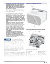
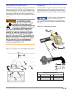
High gas pressure switch – With the burner fi ring
and a manometer attached to the test port nearest
the high pressure switch, gradually increase the
gas pressure until the high pressure switch opens
and shuts the burner off. Note the pressure and
manually reset the switch. The high gas pressure
switch should be set at one and one half times the
high fi re manifold pressure (see nameplate data in
Figure 1 or set switch as determined by testing).
Leak-test valve – With the burner fi ring and
manometer attached to the leak-test valve port, turn
the burner electrical switch off and observe that
the gas pressure does not increase after several
minutes. This proves total closure of the main gas
valve.
Flame safeguard safety lockout – Simulate a
fl ame failure by turning the main gas supply off. The
control should shut the burner off on safety within
the safety lockout time.
Flame sensor circuit (fl ame rod) – With the
burner power switch turned off, refer to the wiring
diagram supplied with the control and locate the
sensor connection terminals. Place DC voltmeter
probes in the fl ame amplifi er test jacks. With the
burner fi ring, the fl ame signal should be steady and
at least 1.25 VDC.
Flame sensor circuit (UV scanner) – With the
burner power switch turned off, refer to the wiring
diagram supplied with the control and locate the
sensor connection terminals. Place DC voltmeter
probes in the fl ame amplifi er test jacks. With the
burner fi ring, the fl ame signal should be steady and
at least 1.25 VDC.
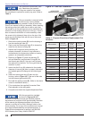
Use Test Instruments to Set Combustion
Verify that all boiler sections, canopy, and access plates
or doors are fully equipped with gaskets and sealed
against any leakage, which could affect the combustion
test results. Before making these tests, operate the
burner for several minutes to allow the heating system
temperature to stabilize or nearly reach steady-state
levels. Record all results in the start-up log for future
reference.
Draft – Set the breech or furnace pressure to the
level specifi ed by the appliance manufacturer. Typical
example: +0.10” W. C.
6.
7.
8.
9.
10.
Oxygen – For both low fi re and high fi re it is
recommended that you measure the oxygen (O
2
) early
in the test sequence because high levels of carbon
monoxide can be created at very low or even very high
O
2
levels. The typical operating range is between 2.5%
– 4.5 %. The equivalent carbon dioxide (CO
2
) operating
range is 9% – 10.5%.
High excess air levels reduce the
fl ame’s UV output and the scanner
signal that proves the burner is fi ring.
Carbon monoxide (CO) – An operating range of 0 -50
PPM is recommended for the burner. The maximum
carbon monoxide (CO) level permitted in the fl ue gas by
the UL 795 Standard is 400 PPM (0.04%).
Stack Temperature – The stack temperature should be
within the range specifi ed by the appliance manufacturer.
It is infl uenced by input fi ring rate, fl ame shape, excess
air ratio, and cleanliness of boiler fl ue passages. This
temperature, combined with the ambient temperature,
and O
2
% (or CO
2
) is used in calculating the appliance
effi ciency.
Recommended Combustion Test Sequence
Adjust the draft or breech pressure to the appliance
manufacturer’s recommended level.
Measure the carbon monoxide level and adjust
air settings, if necessary, to regulate it to about 50
PPM for a starting point.
Measure the O
2
or CO
2
at the 50 PPM CO level.
For this discussion, assume the O
2
is 1.5% (11%
CO
2
).
Open the air adjustment until the O
2
level is
increased by at least 1% or to 3% O
2
(whichever
is higher). This should reduce the CO level and
provide a margin of reserve air to accommodate
variable conditions.
Sample the CO level again. It should be in the 0 to
20 PPM range.
Check the draft to ensure it still meets
specifi cations. If a major change in draft is
required, repeat the above steps.
Perform any fi nal adjustments and lock the air
settings securely. Run the burner through several
cycles to verify prompt ignition and stable burner
operation.
1.
2.
3.
4.
5.
6.
7.
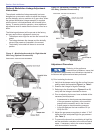
Always use calibrated test
instruments to set combustion
levels. Verify that test instruments are calibrated and
in good working condition. If not already provided, drill
test access holes in the fl ue pipe near the breech (or
upstream of the boiler breech damper, if applicable) and
in the front mounting plate area for fi rebox pressure. Be
careful not to damage any water-backed surface.
Section: Start the Burner