


Manual 2100-532B
Page 46 of 46
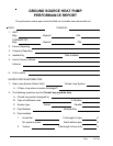
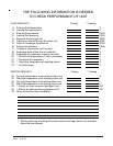
THE FOLLOWING INFORMATION IS NEEDED
TO CHECK PERFORMANCE OF UNIT
FLUID SIDE DATA Cooling ** Heating
9. Entering fluid temperature F
10. Leaving fluid temperature F
11. Entering fluid pressure PSIG
12. Leaving fluid pressure PSIG
13. Pressure drop through coil PSIG
14. Gallons per minute through the water coil GPM
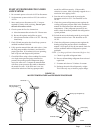
15. Liquid or discharge line pressure PSIG
16. Suction line pressure PSIG
17. Voltage at compressor (unit running) V
18. Amperage draw at line side of contactor A
19. Amperage at compressor common terminal A
20. * Suction line temperature 6” from compressor F
21. * Superheat at compressor F
22. * Liquid line temperature at metering device F
23. * Coil subcooling F
INDOOR SIDE DATA Cooling ** Heating
24. Dry bulb temperature at air entering indoor coil F
25. Wet bulb temperature of air entering indoor coil F
26. Dry bulb temperature of air leaving indoor coil F
27. Wet bulb temperature of air leaving indoor coil F
28. * Supply air static pressure (packaged unit) WC
29. * Return air static pressure (packaged unit) WC
30. Other information about installation
** When performing a heating test insure that second stage heat is not activated.
* Items that are optional