


Manual 2100-532B
Page 23 of 46
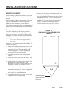
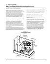
START UP
DESCRIPTION OF STANDARD
EQUIPMENT
LOW PRESSURE SWITCH
NOTE: This unit is supplied with two low pressure
switches installed, a 45 PSIG and a 60 PSIG.
The 60 PSIG is wired into the system. This switch is
suitable for ground water (pump and dump), and water
loop (boiler/tower applications).
To avoid nuisance lockouts for ground loop application
with antifreeze, the 60 PSIG switch should be
disconnected and connect the 45 PSIG switch.
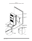
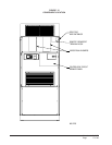
The leads for both switches are located in the lower
electrical connection panel. The switch bodies are
marked with pressure settings. The 60 PSIG switch has
blue leads. The 45 PSIG switch has yellow leads.
HIGH PRESSURE SWITCH
This unit is equipped with a high pressure switch that
will stop the compressor in the event of abnormal high
pressure occurrences.
The high and low pressure switches are included in a
lockout circuit that is resettable from the room
thermostat.
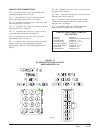
COMPRESSOR CONTROL MODULE
The compressor control module is standard on models
covered by this manual. The compressor control is an
anti-short cycle/lockout timer with high and low
pressure switch monitoring and alarm relay output.
ADJUSTABLE DELAY ON MAKE AND BREAK
TIMER
On initial power up or any time power is interrupted to
the unit, the delay on make period begins, which will be
2 minutes plus 10% of the delay on break setting. When
the delay on make is complete and the high pressure
switch (and low pressure switch, if employed) is closed,
the compressor contactor is energized. Upon shutdown,
the delay on break timer starts and prevents restart until
the delay on break and delay on make periods have
expired.
During routine operation of the unit with no power
interruptions the compressor will operate on demand
with no delay.
HIGH PRESSURE SWITCH AND LOCKOUT
SEQUENCE
If the high pressure switch opens, the compressor
contactor will de-energize immediately. The lockout
timer will go into a soft lockout and stay in soft lockout
until the high pressure switch closes and the delay on
break time has expired. If the high pressure switch
opens again in the same operating cycle, the unit will go
into manual lockout condition and the alarm relay
circuit will energize. Recycling the wall thermostat
resets the manual lockout.
LOW PRESSURE SWITCH, BYPASS AND
LOCKOUT SEQUENCE
If the low pressure switch opens for more than 120
seconds, the compressor contactor will de-energize and
go into a soft lockout. Regardless the state of the low
pressure switch, the contactor will reenergize after the
delay on make time delay has expired. If the low
pressure switch remains open, or opens again for longer
than 120 seconds, the unit will go into manual lockout
condition and the alarm relay circuit will energize.
Recycling the wall thermostat resets the manual lockout.
ALARM RELAY OUTPUT
Alarm terminal is output connection for applications
where alarm relay is employed. This terminal is
powered whenever compressor is locked out due to HPC
or LPC sequences as described.
Note: Both high and low pressure switch controls are
inherently automatic reset devices. The high
pressure switch and low pressure switch cut out
and cut in settings are fixed by specific air
conditioner or heat pump unit model. The
lockout feature, both soft and manual, are a
function of the Compressor Control Module.
ADJUSTMENTS
ADJUSTABLE DELAY ON MAKE AND DELAY
ON BREAK TIMER
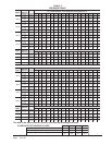
The potentiometer is used to select delay on break time
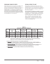
from 30 seconds to 5 minutes. Delay on Make (DOM)
timing on power up and after power interruptions is
equal to 2 minutes plus 10% of Delay on Break (DOB)
setting. See Delay on Make Timing chart on page 24.
During routine operation of the unit with no power
interruptions the compressor will operate on demand
with no delay.