


Manual 2100-532B
Page 18 of 46
WIRING – MAIN POWER
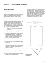
Refer to the unit rating plate and/or Table 2 for wire
sizing information and maximum fuse or “HACR Type”
circuit breaker size. Each unit is marked with a
“Minimum Circuit Ampacity”. This means that the
field wiring used must be sized to carry that amount of
current. Depending on the installed KW of electric heat,
there may be two field power circuits required. If this is
the case, the unit serial plate will so indicate. All
models are suitable only for connection with copper
wire. Each unit and/or wiring diagram will be marked
“Use Copper Conductors Only”. These instructions
must be adhered to. Refer to the National Electrical
Code (NEC) for complete current carrying capacity data
on the various insulation grades of wiring material. All
wiring must conform to NEC and all local codes.
The electrical data lists fuse and wire sizes (75°C copper)
for all models, including the most commonly used heater
sizes. Also shown are the number of field power circuits
required for the various models with heaters.
The unit rating plate lists a “Maximum Time Delay
Relay Fuse” or “HACR Type” circuit breaker that is to
be used with the equipment. The correct size must be
used for proper circuit protection, and also to assure that
there will be no nuisance tripping due to the momentary
high starting current of the compressor motor.
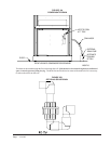
The disconnect access door on this unit may be locked
to prevent unauthorized access to the disconnect.
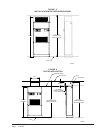
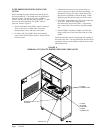
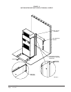
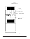
The field wiring connections are located behind the top
panel in the circuit breaker panel. The return air panel
must be removed first. This panel is equipped with a
door switch, which shuts the unit down when it is
removed. The filter rack must be removed next.
WIRING – LOW VOLTAGE WIRING
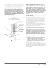
230/208V, 1 PHASE AND 3 PHASE EQUIPMENT
DUAL PRIMARY VOLTAGE TRANSFORMERS
All equipment leaves the factory wired on 240V tap.
For 208V operation, reconnect from 240V to 208V tap.
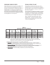
The acceptable operating voltage range for the 240 and
208V taps are as noted in Table 2.
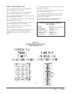
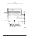
The standard Climate Control Option X is a remote
thermostat connection terminal block. See Figure 14 for
wiring diagram. Compatible thermostats are listed in
Table 3.
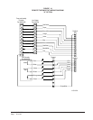
The Climate Control Option D is an electronic,
programmable thermostat. The subbase of the
thermostat is factory wired to the front panel of the unit.
See Figure 15 for wiring diagram. Compatible for use
with Energy Recovery Ventilator or Economizer.
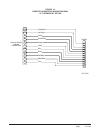
The Climate Control Option H is an electronic,
programmable thermostat and CO
2
controller. The
subbase of the thermostat and CO
2
controller are factory
wired to the front panel of the unit. See Figure 16 for
wiring diagram.
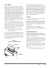
GENERAL
This unit is equipped with a variable speed ECM motor.
The motor is designed to maintain rated airflow up to
the maximum static allowed. It is important that the
blower motor plugs are not plugged in or unplugged
while the power is on. Failure to remove power prior
to unplugging or plugging in the motor could result in
motor failure.
NOTE: The voltage should be measured at the field
power connection point in the unit and while
the unit is operating at full load (maximum
amperage operating condition).
TABLE 2
OPERATING VOLTAGE RANGE
PATEGNAR
V042612-352
V802781-022
TABLE 3
WALL THERMOSTATS
tatsomrehTserutaeFtnanimoderP
060-3048
)544-0211(
taeHegats3;looCegats3
cinortcelEelbammargorP-noN/elbammargorP
lanoitnevnoCroPH
revoegnahclaunaMrootuA
CAUTION
Do not plug in or unplug blower motor con-
nectors while the power is on. Failure to do
so may result in motor failure.