


Manual 2100-532B
Page 33 of 46
6
10
11
8
9
12
7
MIS-2749
OPEN LOOP
(Well System Applications)
WATER CONNECTIONS
It is very important that an adequate supply of clean,
noncorrosive water at the proper pressure be provided
before the installation is made. Insufficient water, in
the heating mode for example, will cause the low
pressure switch to trip, shutting down the heat pump. In
assessing the capacity of the water system, it is
advisable that the complete water system be evaluated
to prevent possible lack of water or water pressure at
various household fixtures whenever the heat pump
turns on. All plumbing to and from the unit is to be
installed in accordance with local plumbing codes. The
use of plastic pipe, where permissible, is recommended
to prevent electrolytic corrosion of the water pipe.
Because of the relatively cold temperatures encountered
with well water, it is strongly recommended that the
water lines connecting the unit be insulated to prevent
water droplets form condensing on the pipe surface.
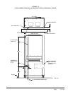
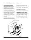
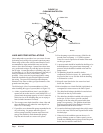
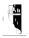
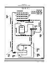
Refer to piping, Figure 23. Slow closing
Solenoid
Valve (6)
with a 24V coil provides on/off control of the
water flow to the unit. Refer to the wiring diagram for
correct hookup of the valve solenoid coil.
Constant Flow Valve (7)
provides correct flow of
water to the unit regardless of variations in water
pressure. Observe the water flow direction indicated by
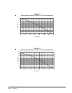
the arrow on the side of the valve body. Table 7 is a
table showing the flow rate of each valve. Two
constant flow rate valves may be installed in parallel to
increase the flow. For example, when a 8603-007 (6
GPM) and 8603-011 (5 GPM) are installed in parallel
the total flow will be 11 GPM.
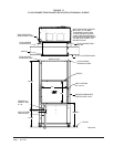
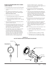
FIGURE 23
PIPING DIAGRAM
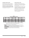
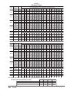
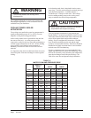
TABLE 7
CONSTANT FLOW VALVES
1 The pressure drop through the constant flow valve will
vary depending on the available pressure ahead of the
valve. Unless minimum of 15 psig is available
immediately ahead of the valve, no water will flow.
.oNtraP
elbaliavA.niM
GISPerusserP
etaRwolF
MPG
-VFC5 51 1 5
6-VFC51 1 6
7-VFC51 1 7
9-VFC51 1 9
Strainer (5)
installed upstream of
constant flow valve
(7)
to collect foreign material which would clog the
flow valve orifice.
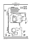
Figure 22 shows the use of
shutoff valves (9)
and
(11)
,
on the in and out water lines to permit isolation of the
unit from the plumbing system should future service
work require this. Globe valves should not be used as
shutoff valves because of the excessive pressure drop
inherent in the valve design. Instead use gate or ball
valves as shut-offs so as to minimize pressure drop.
Drain cock (8)
and
(10)
, and tees have been included
to permit acid cleaning the refrigerant-to-water coil
should such cleaning be required. See
WATER
CORROSION
section.
Drain cock (12)
provides access to the system to check
water flow through the constant flow valve to insure
adequate water flow through the unit. A water meter is
used to check the water flow rate.