


Manual 2100-532B
Page 31 of 46
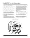
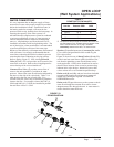
START UP PROCEDURE FOR CLOSED
LOOP SYSTEM
1. Be sure main power to the unit is OFF at disconnect.
2. Set thermostat system switch to OFF, fan switch to
AUTO.
3. Move main power disconnect to ON. Except as
required for safety while servicing,
Do not open
the unit disconnect switch.
4. Check system air flow for obstructions.
A.
Move thermostat fan switch to ON. Blower runs.
B. Be sure all registers and grilles are open.
C. Move thermostat fan switch to AUTO. Blowing
should stop.
5. Flush, fill and pressurize the closed loop system as
outlined in manual 2100-099.
6. Fully open the manual inlet and outlet valves. Start
the loop pump module circulator(s) and check for
proper operation. If circulator(s) are not operating,
turn off power and diagnose the problem.
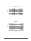
7. Check fluid flow using a direct reading flow meter
or a single water pressure gauge, measure the
pressure drop at the pressure/temperature plugs
across the water coil. Compare the measurement
with flow versus pressure drop table to determine
the actual flow rate. If the flow rate is too low,
recheck the selection of the loop pump module
model for sufficient capacity. If the module
selection is correct, there is probably trapped air or a
restriction in the piping circuit.
8. Start the unit in cooling mode by moving the
thermostat switch to cool. Fan should be set for
AUTO.
9. Check the system refrigerant pressures against the
cooling refrigerant pressure table in the installation
manual for rated water flow and entering water
temperatures. If the refrigerant pressures do not
match, check for airflow problem then refrigeration
system problem.
10. Switch the unit to the heating mode by moving the
thermostat switch to heat. Fan should be set for
AUTO.
11. Check the refrigerant system pressures against the
heating refrigerant pressure table in installation
manual. Once again, if they do not match, check for
airflow problems and then refrigeration system
problems.
NOTE: If a charge problem is determined (high or low):
A. Check for possible refrigerant leaks.
B. Recover all remaining refrigerant from unit and
repair leak.
C. Evacuate unit down to 29 inches of vacuum
D. Recharge the unit with refrigerant by weight.
This is the only way to insure a proper charge.
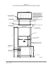
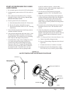
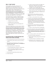
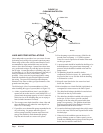
FIGURE 20
WATER TEMPERATURE and PRESSURE PROCEDURE
10
120
110
100
90
80
70
60
50
40
30
20
0
Pete's test plug
Retaining cap, hand tighten only
Test plug cap
Barbed 90° adapter
MIS-2622
with guage adaptor
Dial face pressure guage
Thermometer