


Manual 2100-532B
Page 34 of 46
WELL PUMP SIZING
Strictly speaking, sizing the well pump is the
responsibility of the well drilling contractor. It is
important, however, that the HVAC contractor be
familiar with the factors that determine what size pump
will be required. Rule of thumb estimates will
invariably lead to under or oversized well pumps.
Undersizing the pump will result in inadequate water to
the whole plumbing system but with especially bad
results to the heat pump – NO HEAT / NO COOL calls
will result. Oversized pumps will short cycle and could
cause premature pump motor or switch failures.
The well pump must be capable of supplying enough
water and at an adequate pressure to meet competing
demands of water fixtures. The well pump must be
sized in such a way that three requirements are met:
1. Adequate flow rate in GPM.
2. Adequate pressure at the fixture.
3. Able to meet the above from the depth of the
well-feet of lift.
The pressure requirements put on the pump are directly
affected by the diameter of pipe being used, as well as,
by the water flow rate through the pipe. The work sheet
included in manual 2110-078 should guarantee that the
well pump has enough capacity. It should also ensure
that the piping is not undersized which would create too
much pressure due to friction loss. High pressure losses
due to undersized pipe will reduce efficiency and
require larger pumps and could also create water noise
problems.
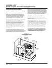
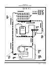
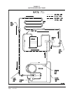
SYSTEM START UP PROCEDURE FOR
OPEN LOOP APPLICATIONS
1. Be sure main power to the unit is OFF at disconnect.
2. Set thermostat system switch to OFF, fan switch to
AUTO.
3. Move main power disconnect to ON. Except as
required for safety while servicing – do not open the
unit disconnect switch.
4. Check system airflow for obstructions.
A.
Move thermostat fan switch to ON. Blower runs.
B. Be sure all registers and grilles are open.
C. Move thermostat fan switch to AUTO. Blower
should stop.
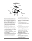
5. Fully open the manual inlet and outlet valves.
6. Check water flow.
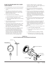
A. Connect a water flow meter to the drain cock
between the constant flow valve and the
solenoid valve. Run a hose from the flow meter
to a drain or sink. Open the drain cock.
B. Check the water flow rate through constant flow
valve to be sure it is the same as the unit is rated for.
C. When water flow is okay, close drain cock and
remove the water flow meter. The unit is now
ready to start.
7. Start the unit in cooling mode by moving the
thermostat switch to cool. Fan should be set for
AUTO.
A. Check to see the solenoid valve opened.
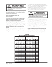
8. Check the system refrigerant pressures against the
cooling refrigerant pressure table in the installation
manual for rated water flow and entering water
temperatures. If the refrigerant pressures do not
match, check for airflow problem that refrigeration
system problem.
9. Switch the unit to the heat mode by moving the
thermostat switch to heat. Fan should be set for
AUTO.
A. Check to see the solenoid valve opened again.
10. Check the refrigerant system pressures against the
heating refrigerant pressure table in installation
manual. Once again, if they do not match, check for
air flow problems and then refrigeration system
problems.
NOTE: If a charge problem is determined (high or low):
A. Check for possible refrigerant loss.
B. Recover all remaining refrigerant from unit and
repair leak.
C. Evacuate unit down to 29 inches of vacuum.
D. Recharge the unit with refrigerant by weight.
This is the only way to insure proper charge.