


Manual 2100-532B
Page 36 of 46
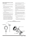
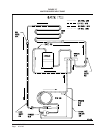
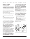
MIS-2750
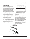
Hose Bib (A)
Hose Bib (B)
Pump
Isolation Valve
TO WATER COIL
FROM WATER COIL
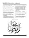
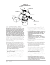
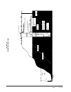
LAKE AND POND INSTALLATIONS
Lakes and ponds can provide a low cost source of water
for heating and cooling with a ground water heat pump.
Direct usage of the water without some filtration is not
recommended as algae and turbid water can foul the
water to freon heat exchanger. Instead, there have been
very good results using a dry well dug next to the water
line or edge. Normal procedure in installing a dry well
is to backhoe a 15 to 20 foot hole adjacent to the body of
water (set backhoe as close to the water’s edge as
possible). Once excavated, a perforated plastic casing
should be installed with gravel backfill placed around
the casing. The gravel bed should provide adequate
filtration of the water to allow good performance of the
ground water heat pump.
The following is a list of recommendations to follow
when installing this type of system (Refer to Figure 25):
A. A lake or pond should be at least 1 acre (40,000 a
square feet) in surface area for each 50,000 BTUs of
ground water heat pump capacity or have 2 times the
cubic feet size of the dwelling that you are trying to
heat (includes basement if heated).
B. The average water depth should be a least 4 feet and
there should be an area where the water depth is at
least 12 to 15 feet deep.
C. If possible, use a submersible pump suspended in the
dry well casing. Jet pumps and other types of
suction pumps normally consume more electrical
energy than similarly sized submersible pumps.
Pipe the unit the same as a water well system.
D. Size the pump to provide necessary GPM for the
ground water heat pump. A 12 GPM or greater
water flow rate is required on all modes when used
on this type system.
E. A pressure tank should be installed in dwelling to be
heated adjacent to the ground water heat pump. A
pressure switch should be installed at the tank for
pump control.
F. All plumbing should be carefully sized to
compensate for friction losses, etc., particularly if
the pond or lake is over 200 feet from the dwelling
to be heated or cooled.
G. Keep all water lines below low water level and
below the frost line.
H. Most installers use 4-inch filed tile (rigid plastic or
corrugated) for water return to the lake or pond.
I. The drain line discharge should be located at least
100 feet from the dry well location.
J. The drain line should be installed with a slope of 2
inches per 10 feet of run to provide complete
drainage of the line when the ground water heat
pump is not operating. This gradient should also
help prevent freezing of the discharge where the
pipe terminates above the frost line.
K. Locate the discharge high enough above high water
level so the water will not back up and freeze inside
the drain pipe.
L. Where the local conditions prevent the use of a
gravity drainage system to a lake or pond, you can
instead run standard plastic piping out into the pond
below the frost and low water level.
FIGURE 24
CLEANING WATER COIL